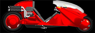
Welcome to Matus1976's Akira Bike Project - Building a fully functional high performance recumbent motorcycle inspired by Kaneda's ride in "Akira"
Update 13


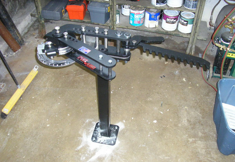
First, some new tools. For tube bending, which is necessary for frame construction, I bought the PRO TOOLS Model 105 tubing bender. http://www.pro-tools.com/105.htm
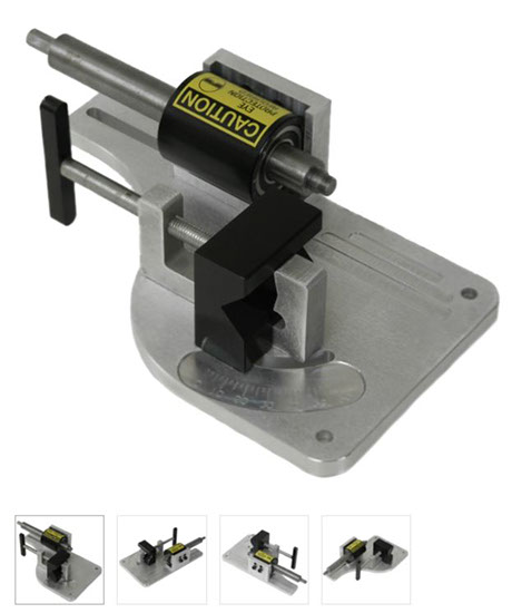
As well as one of their tubing notchers
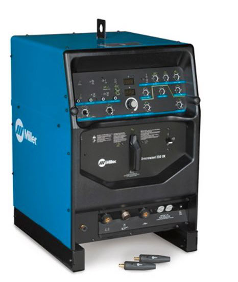
Next up was a Miller TIG Welder, which I've been eyeing for about 3 years now.
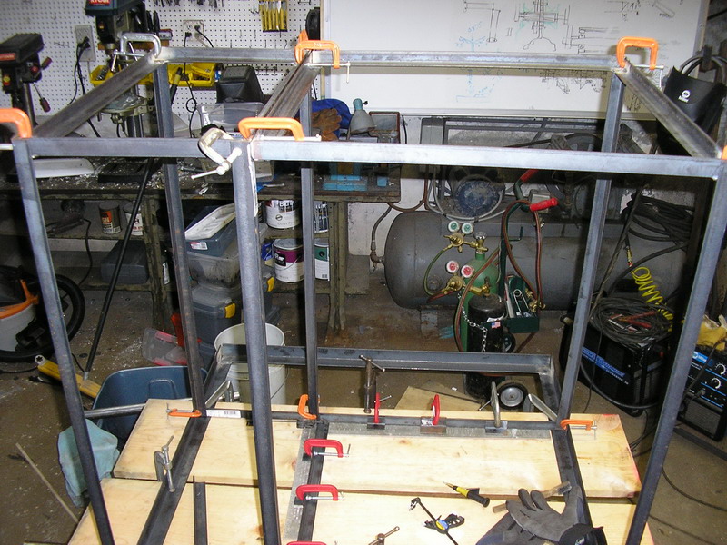
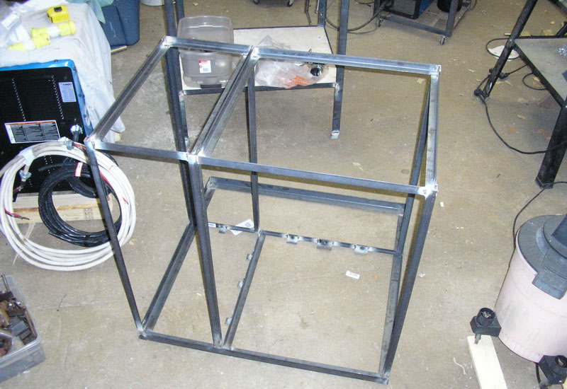
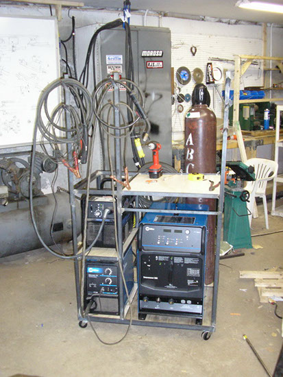
My existing welding cart, which only held a small Miller MIG welder and my plasma torch was obviously not enough for this monster. So here's the new welding cart jigged and waiting for welding.
After welding
The finished assembly, nice!
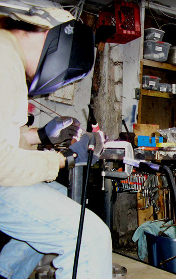
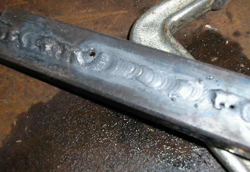
Trying out the new TIG welder
1st attempt, I was very impressed, it was like spreading butter. TIG Welders give you much more control over the variables of the welding, you can alter the heat being applied to your work area separately from the rate of feed of the metal being applied and the thickness of the filler metal, but the whole welding process is more complex than the quick and simple MIG welding.
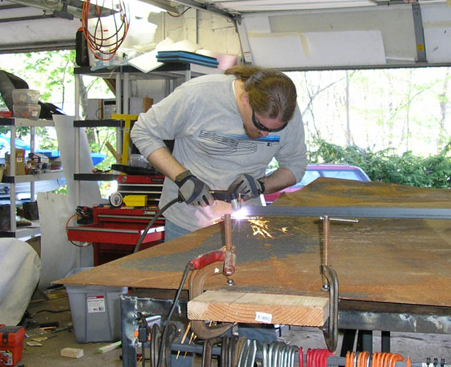
First project after that was to get a new workbench made, which will be necessary for some of the large complex parts coming up (such as the single sided swingarm) First up, cutting the top to my new workbench with the plasma torch
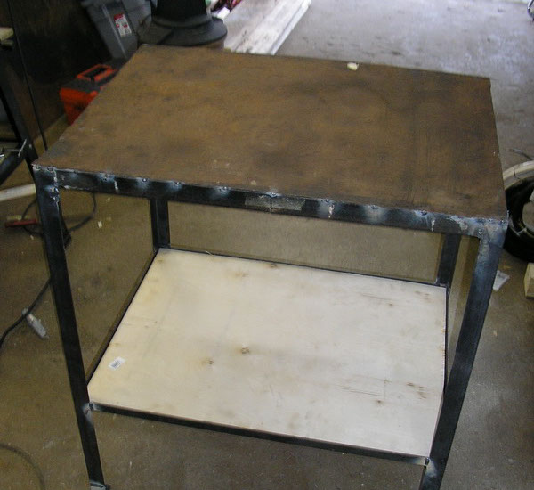
And then the finished workbench, these are heavy duty workbenches. The top is made of angle steel welded into a rectangle but then filled with concrete.
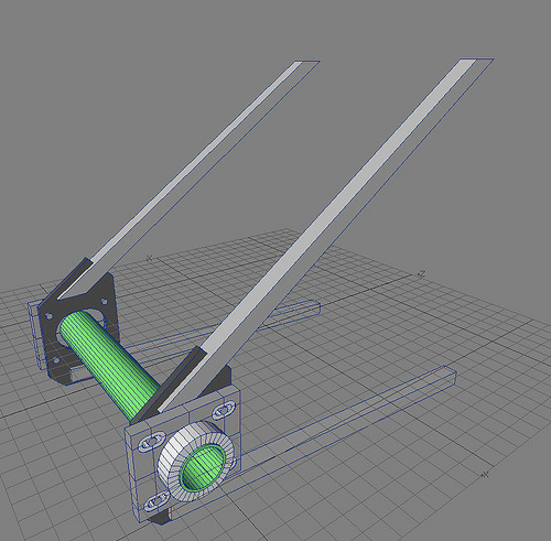
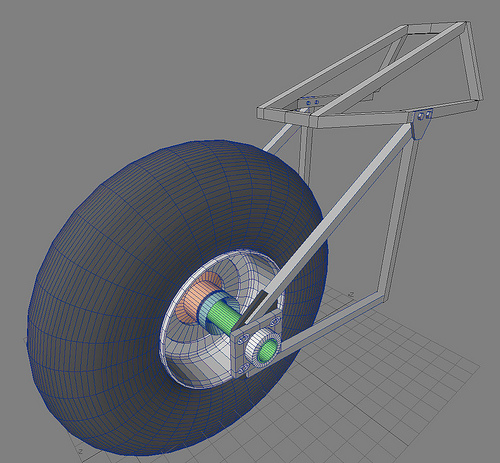
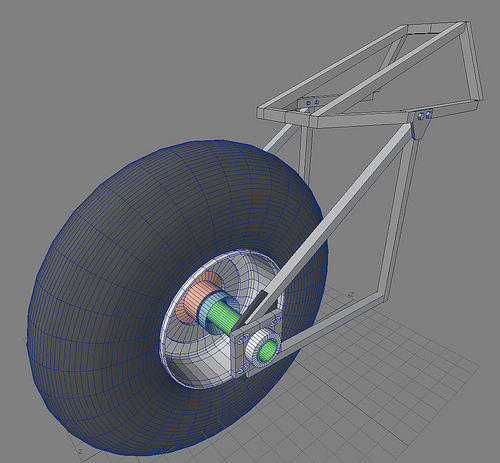
Ok, on to the bike project! The next major step is getting the rear wheel mounted and drive system completed. Here is the rear wheel mounting assembly, the first phase is a hard tail, which will later be updated to softail. This is the last step to get my power prototype to a rolling chassis status. This essentially constitutes a rigid mounted rear wheel (no suspension) with a large hollow spindle (the green tube) The grey square tubes will be 1" mild square tubing, .125" wall thickness, the dark grey plates that intersect those will be welded to the tubes and made up of 3/8" mild steel plating. A large oval will be cut into that to make room for some small adjusting of the spindle (and thus the plane of rotation for the wheel)
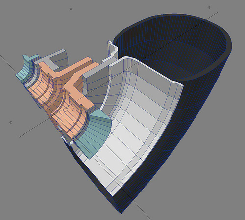
Here is a partial cross section of parts of the rear wheel hub, which will actually hold the wheel + tire on the spindle. The white part is the rim of the wheel. The light grey and orange are both cast aluminum parts that will need to be machined. The dark grey are thrust bearings to the wheel can be held rigidly at the center of the bike. Green parts are also castings that press against the inside of the aluminum brackets mentioned above. Some parts are left out of this, including the radial bearings, but you can see where they will go, in the grooves in the orange hub pieces.
Here is the same image but with a quarter section of the tire as well.
Tire + Wheel + hub and rear frame. Also in this image is the brake rotor and 3 pot caliper.
With the rest of the rear frame pieces I still need to make
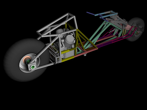
Ultimately the whole thing will look something like this! very cool
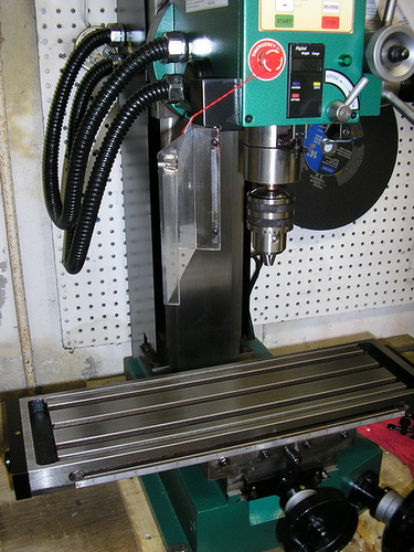
After much consideration, I decided to get a desktop mill and desktop lathe. Considering a single custom fabricated aluminum part can cost from hundreds to thousands of dollars (it's only when you make thousands of them that they get cheap) this seemed the better way to go. Winner for the mill, is the desktop mill from Grizzly Model# G0619
So back to the bike, here is the spindle mount I was making for the rear frame
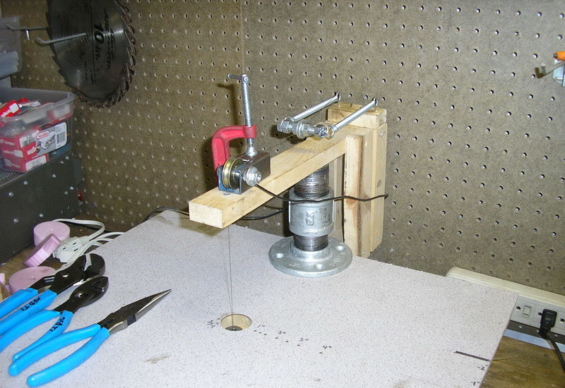
I would need to cut this part out of foam and the cast them out of aluminum, I've been having accuracy issued with my hot wire foam cutter though, and also wanted to add a mechanism which would enable me to rapidly re-feed the wire. I would need to do this in order to cut holes out of the centers of parts. Above you see the red clamp, under that is a small pulley. The hot wire runs over the side of the pulley and down through the wood arm. Loosening the clamp I could slide the pulley around, this made of a quick and easy way to adjust the wire with respect to the table surface to make sure it was perpendicular.
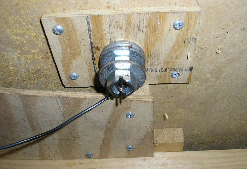
On the underside, a notched nut holds a nail which is threaded through the eye of the wire (these wires are guitar strings - which work great for hot wire foam cutters) the electrical current goes to bolt independent of the nail again making it quick and easy to change.
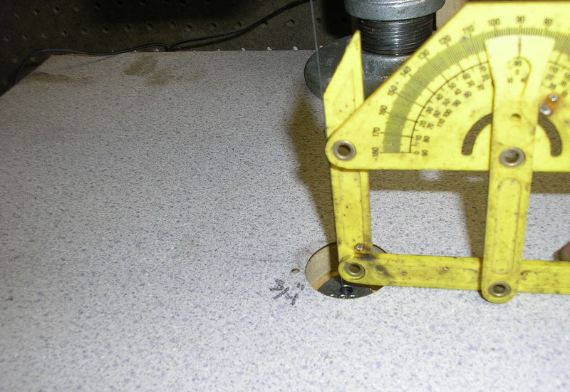
A nice right angle wire!
So, FINALLY, on to some parts! Here is one of the mounting brackets being cut with the foam cutter.
And the foam version ready for casting, my new hot wire foam cutter modifications made this a million times easier.
The kiln in action. I'd like to get a picture of the actual pour of the molten aluminum, but since I'm doing the pouring it's difficult, even with the timer on the camera.
And the result! came out excellent!
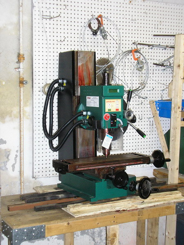
And look what came in!
Transferred to my work bench via hydraulic lift through a very complicated procedure.
Cleaned, bolted to the table, and ready for action
The accessories, it's like Christmas all over again...
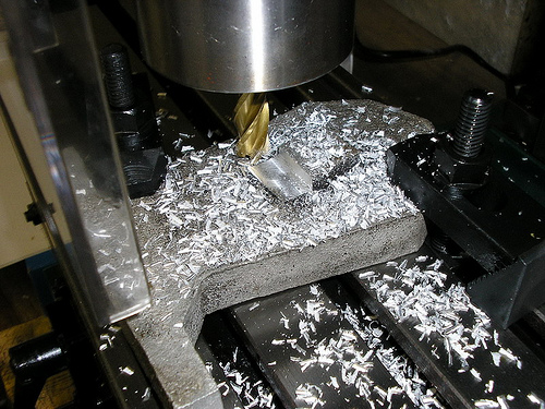
And finally here is the Mill in action, showing what mill's are good for. The work piece is clamped to the table, and the tool is a 4 flute "End Mill" like a drill be but flat at the end and steeper spirals, it can cut sideways just as well as it can plunge cut. It worked great, this is a good quality machine and I think I'll be very happy with it.
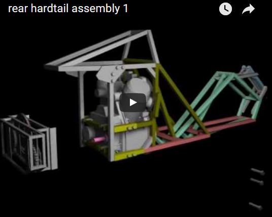
Here, again, is that rear assembly
With all of my designs, I like to actually animate their assembly so I can be sure that no parts will get in each others ways, also the animations come out looking great. Here is the assembly of the rear of the bike. Check out the animation here
Back to the spindle brackets. Here are the two cast brackets
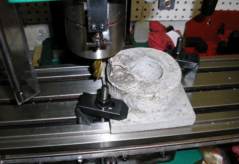
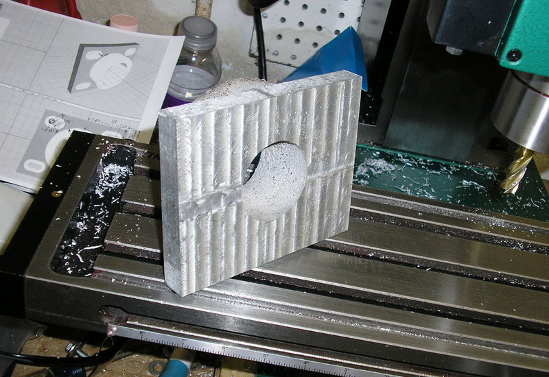
Clamped to the MILLING MACHINE!
Top surfaced machined. Nice and smooth...
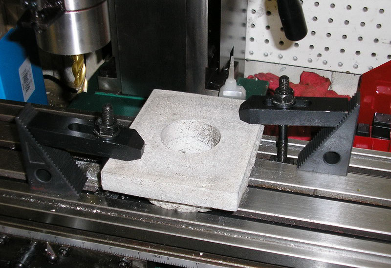
Flipping it over and clamping it down
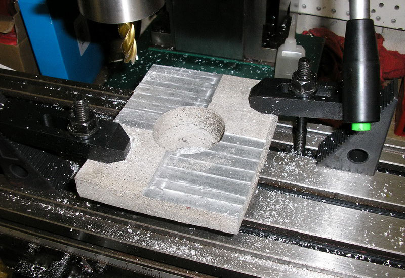
Half of the back side machined
The whole thing done, front, back, and sides are machined nice and smooth. Now just have to do the curved sections on the lathe
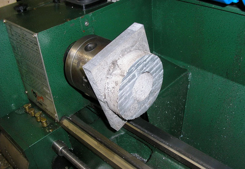
Mounted to the lathe
Outside smoothed out on the lathe. The lathe does this by sliding a small triangular tooth along the edge while the part is rotating, cutting thin layer off. A milling machine, by contrast, spins the cutting tool and moves it into the part.
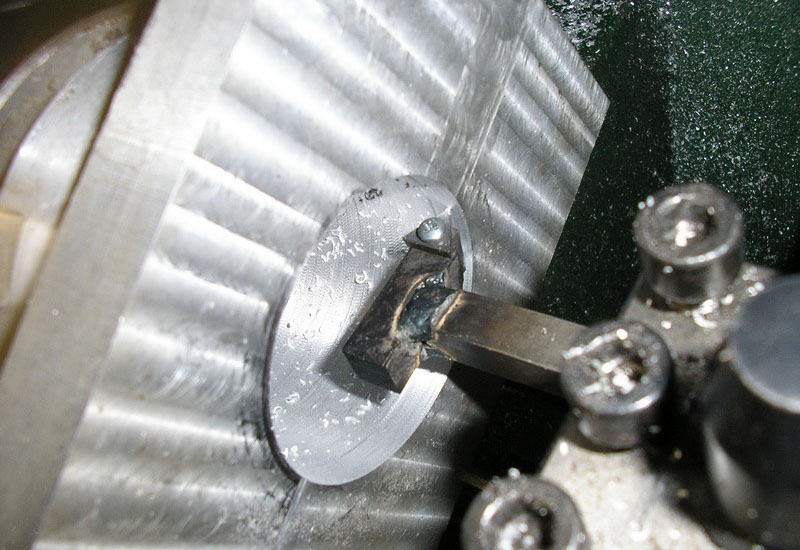
Next was the inside of the mounting bracket. Actually I lacked the appropriate tool I needed for this cut on the inside of a small diameter part. So I just welded one up real quick, not too bad for about 15 minutes. In this picture you can clearly see the successive layers getting scraped away as the triangular cutting tools is moved forward into the part.
Done! just to be sure I took the part which will be the spindle and inserted it into the bracket and it fit great.
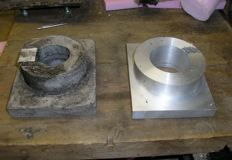
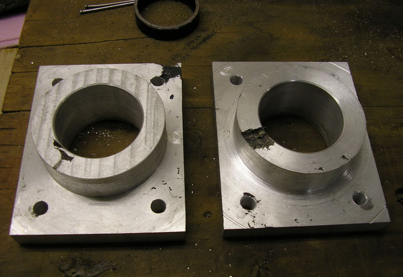
Here is the other bracket, not yet machined, next to the new one after machining, what a difference! This part came out great
A little while later, the next one is done.
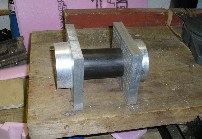
Making sure they both fit together with a section the spindle (the actual spindle will be about 2' long)
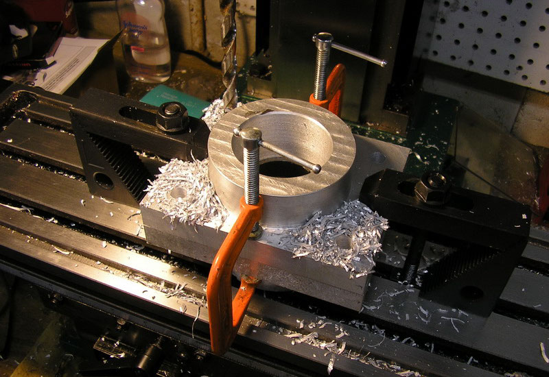
With a small section of the the spindle inserted to make sure they stay lined up, I clamped them tightly together and then clamped the pair to the milling machine. This would ensure both parts matched exactly and then I drilled the mounting holes
And that's it for the brackets! Beautiful! You can see some surface defects here though, as a result of my casting process. These defects do not extend into the part more than a 1/100 of an inch or so, and these parts are way over engineered. Since these parts were made I toured a real aluminum casting foundry nearbye and learned alot of great new tricks.
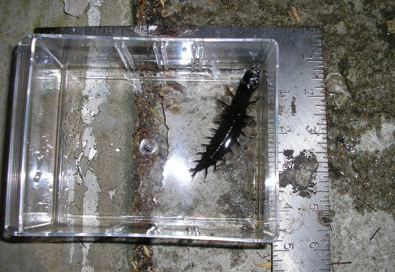
Around this time I had a little visitor to my workshop. WTF is that? Yes, that thing is over 3" long! freaky thing. It's called a Hellgrammite, my brother who fishes knew exactly what it was and informed me. It's the larvae stage of a giant fly, called the Dobson fly, and in this stage it is an aquatic insect. Every few years they all come out of the streams and turn into the fly, for just a few days, mate, lay eggs in the stream, then die. The flies can get up to 5 inches long. From the web, though they look nasty with those giant pinchers, apparently only the males have them and they just use them for holding down the females for mating.
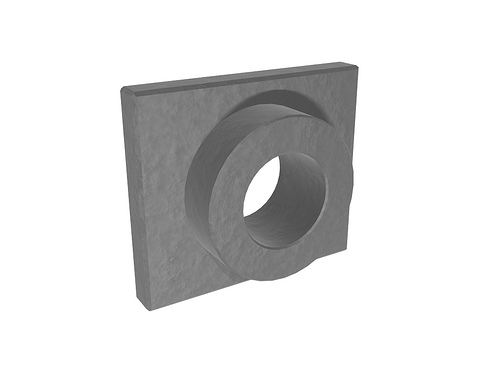
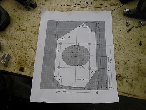
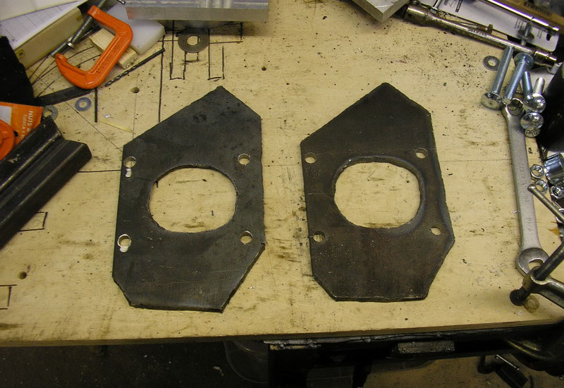
Anyway...On to the next part of the rear hard tail mount, the steel plates that the spindle mounting brackets will bolt to.
After lots of plasma torching, grinding, and drilling, the result...
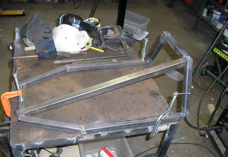
Still needs some work, but on to the rest of the frame. Lots of cutting, careful aligning, and tack-welding later
Last piece added, and welds done.
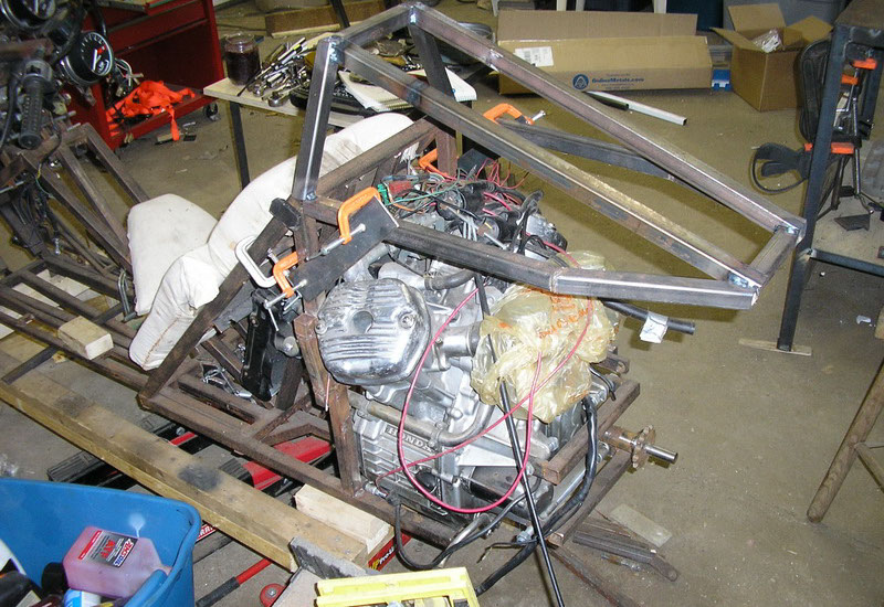
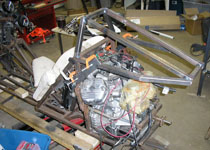
And (temporarily) mounted on the bike!
1 - 53
<
>
A few new tools added to the workshop. A pro-tools tubing bender and notcher, a miller TIG welder, a Grizzly desktop mill and last a desktop lathe. Then onto the bike where I start work on the rear frame making progress to a rolling chassis.
Help bring the fully functional high performance production Akira inspired motorcycle into existence...

Contribute through Amazon affilicate purchases
Donate directly
go to crowdfund for more options
send donations to

