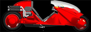
Welcome to Matus1976's Akira Bike Project - Building a fully functional high performance recumbent motorcycle inspired by Kaneda's ride in "Akira"
Update 11


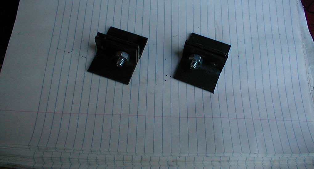
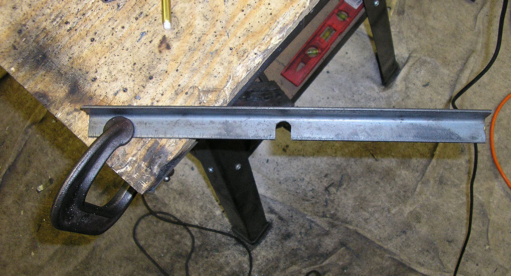
First, a minor improvement on the foot rests. These brackets will go under the sliding foot rests toward the front.
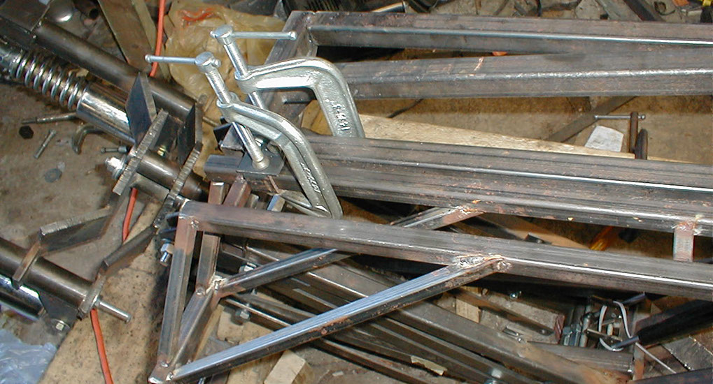
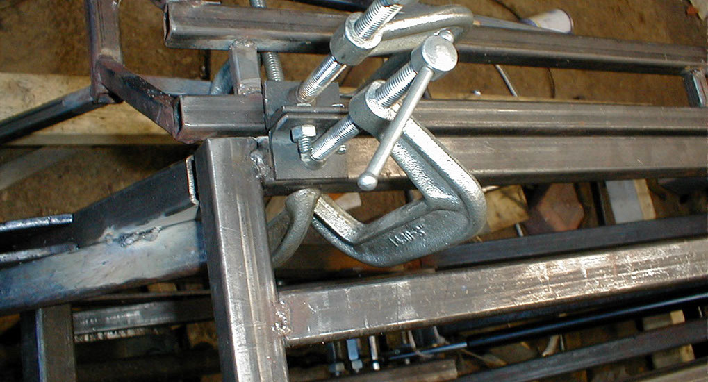
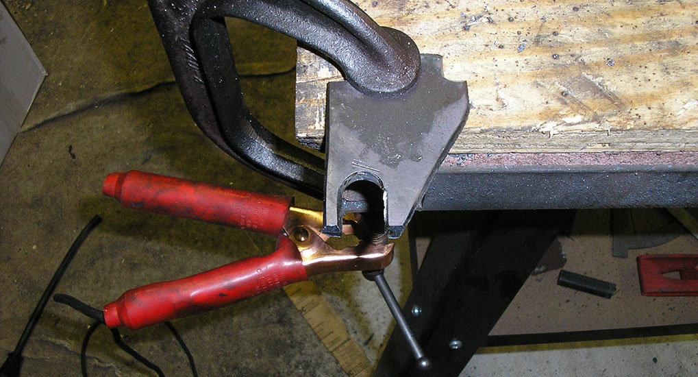
Clamped and getting ready to weld
The other side, and a clearer image, these will help support the weight of the foot rests & riders legs
Both welded on.
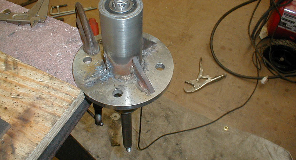
Next, some improvements to the front wheel hub.
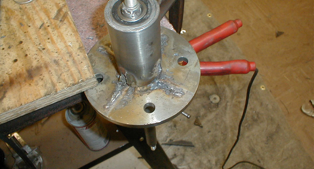
Removing the old poorly welded gussets.
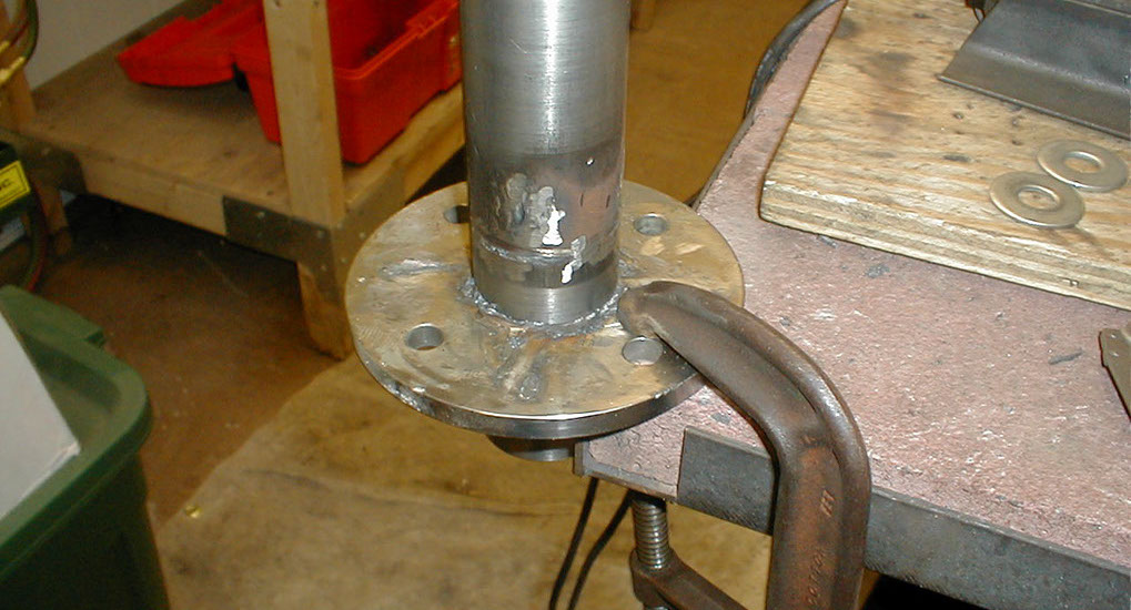
Ready for the update.
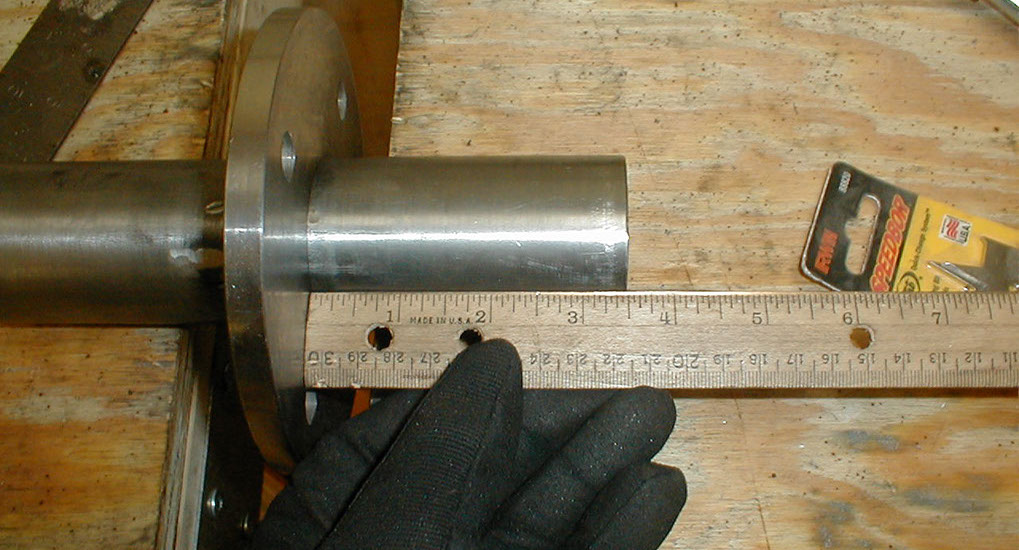
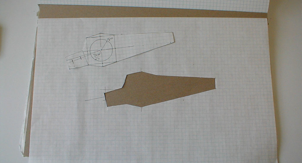
Measuring out.
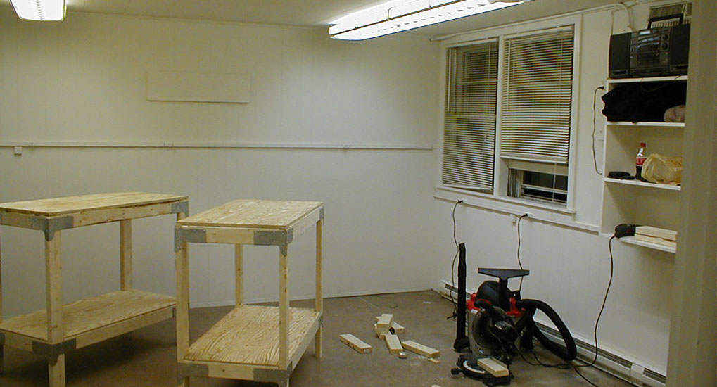
In the new workshop, I built a bunch of these handy durable benches.
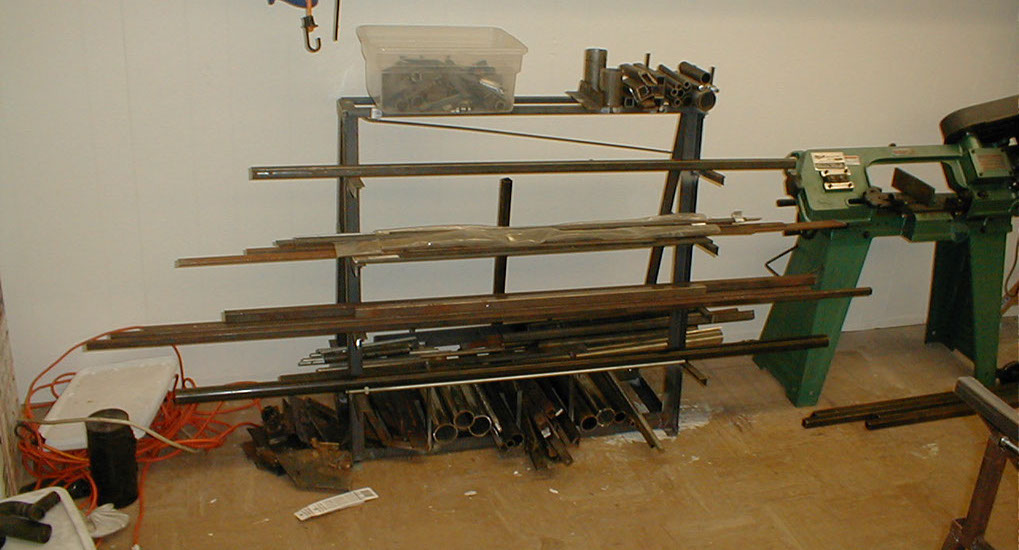
Then a metal rack. Here are the sides of it.
Starting to come together.
Finished metal rack, very useful for organization and to remove clutter.
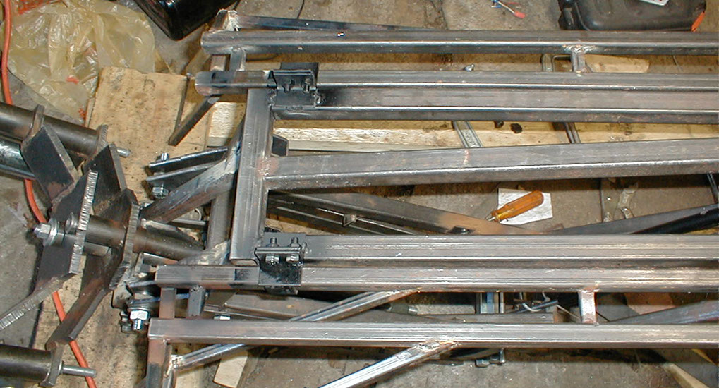
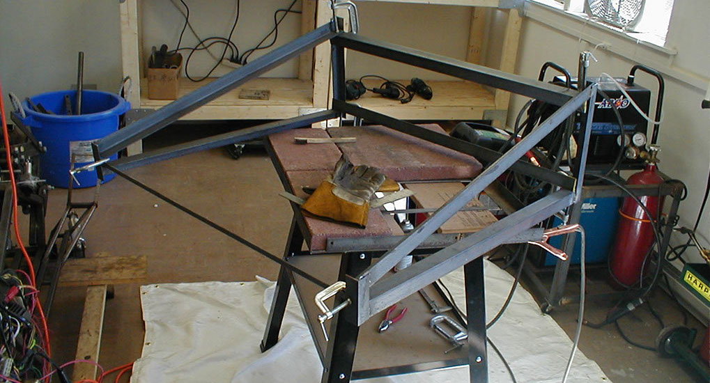
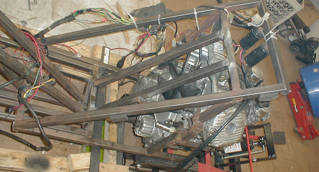
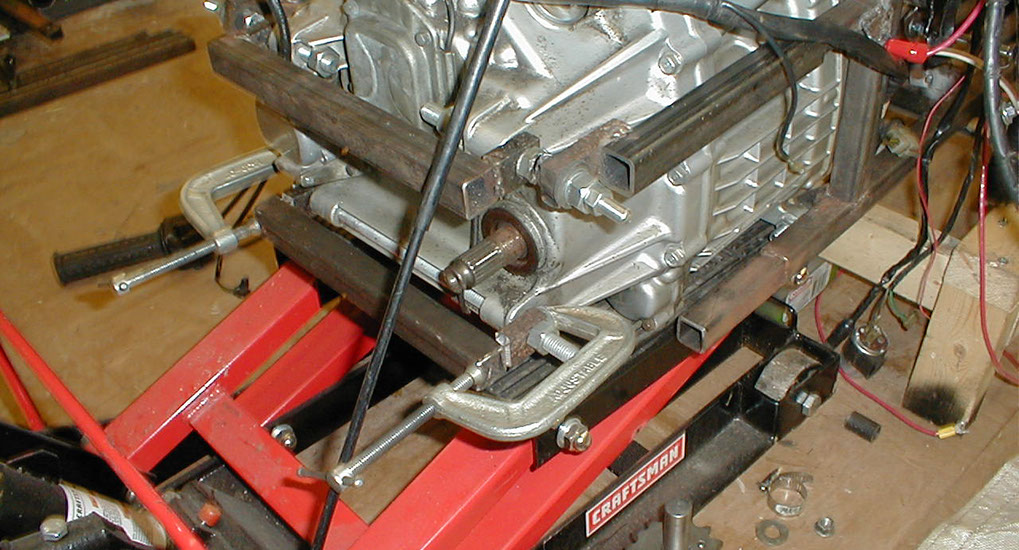
These two main bars were added in front of the engine for additional triangulation and strength.
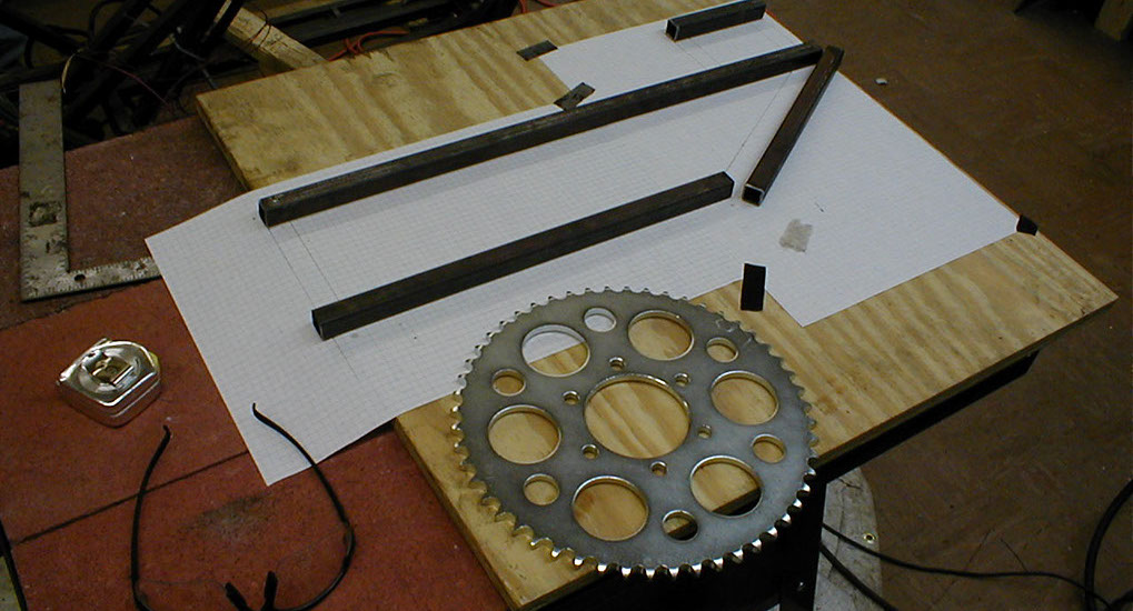
Getting started on the sprocket gear reduction cage. Since my wheel is larger and bike is heavier than the CX500, I'm reducing the gearing for the final drive.
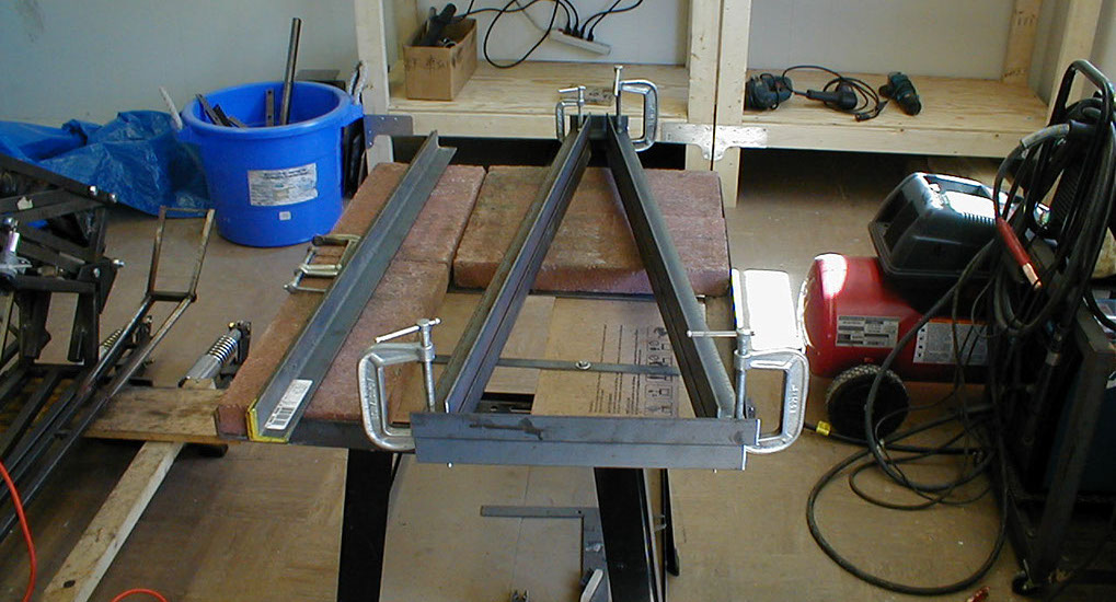
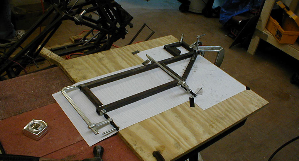
Clamping and getting ready to weld.
Adding some mounts to the rear of the engine.
Getting started on the front wheel caliper mounts.
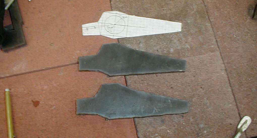
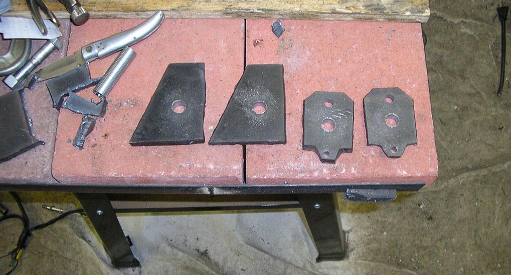
Now cut out of steel with the plasma torch.
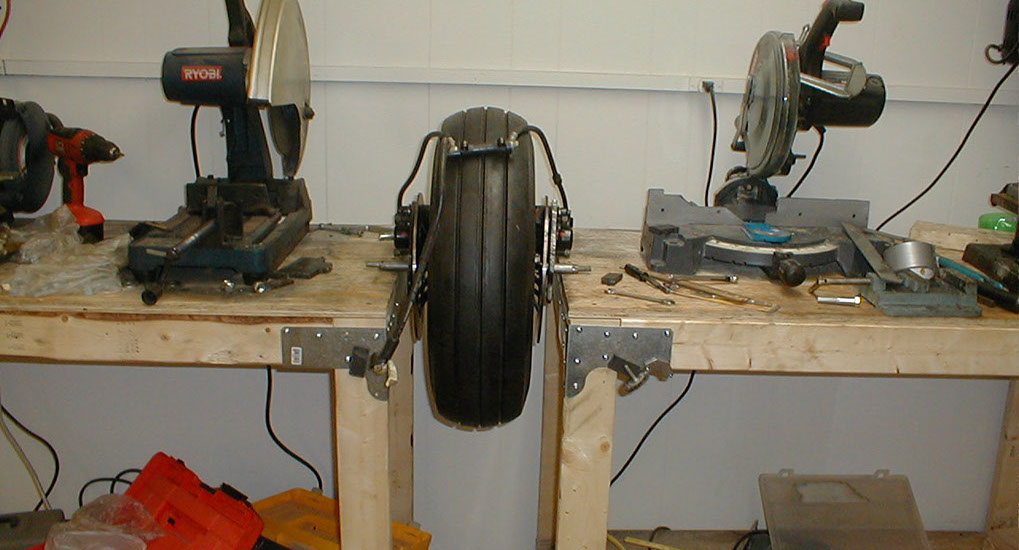
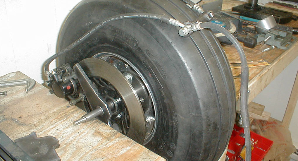
The new front wheel & hub & caliper mounts with brake calipers mounted.
Here is the new hub, caliper and brakes.
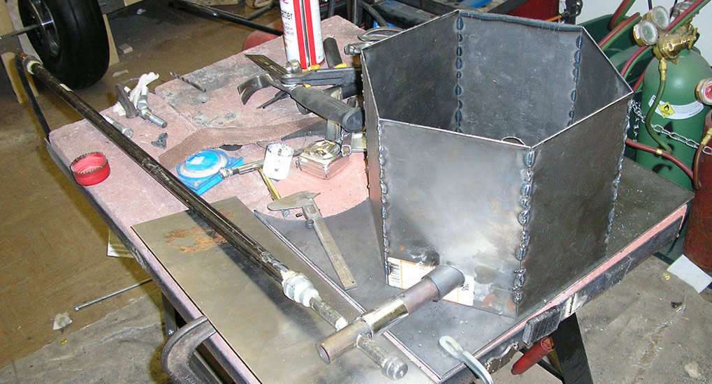
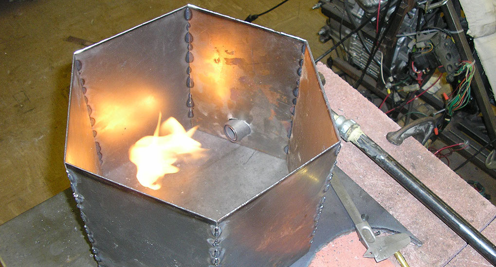
I needed to fabricate some specific aluminum parts, which are costly. After some research I decided to make parts out of lost foam aluminum casting. After some small experimentation I started on building a kiln for melting aluminum.
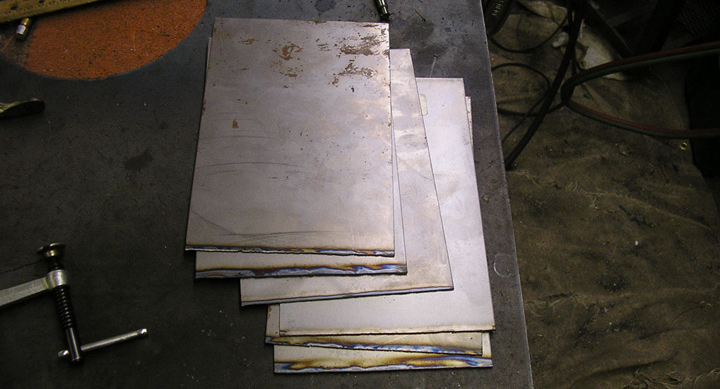
Cutting the walls out.
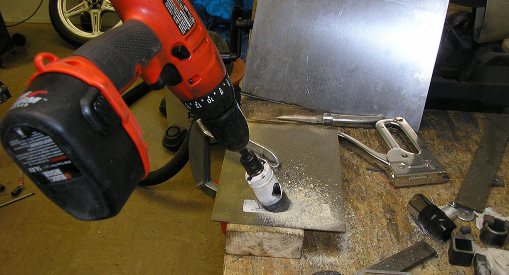
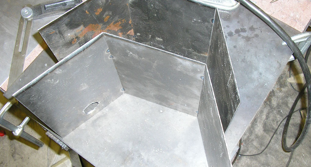
Drilling the feed pipe hole.
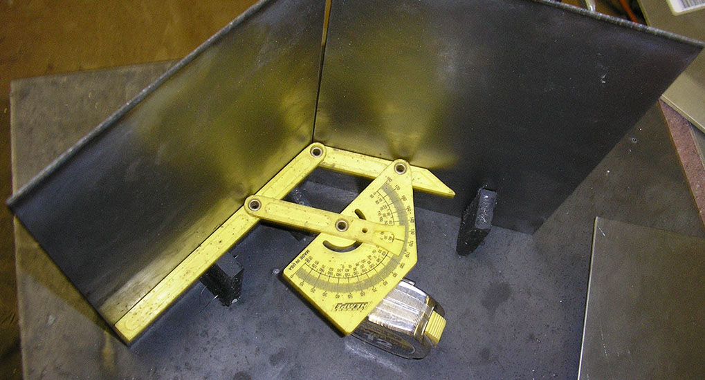
Jigging up the wall plates.
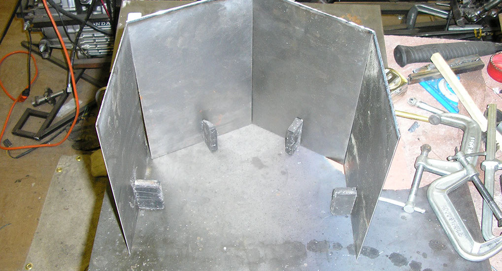
More jigging.
Tack welded.
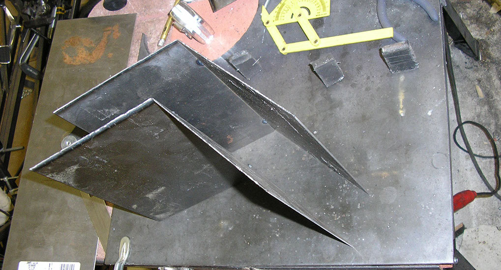
Both outside halves now tack welded.
Combining the two halves to one hexagon unit.
Testing the flame out.
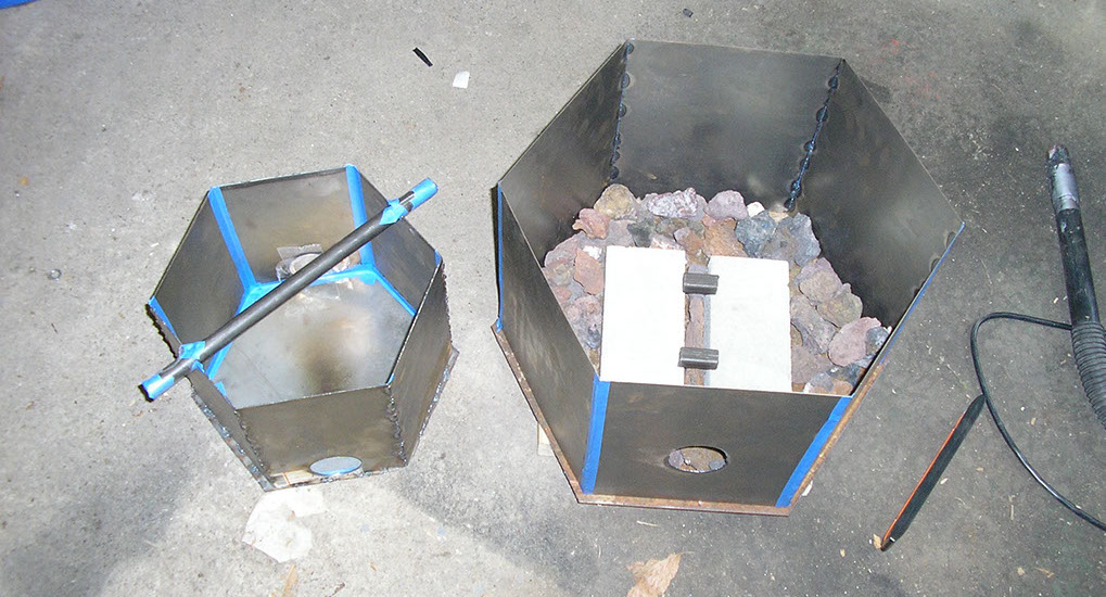
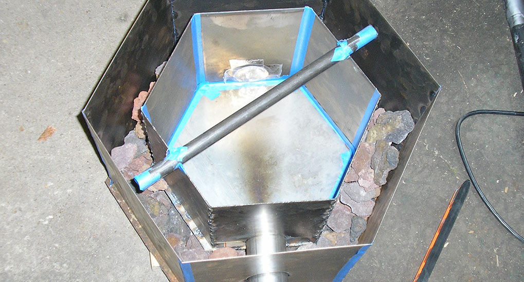
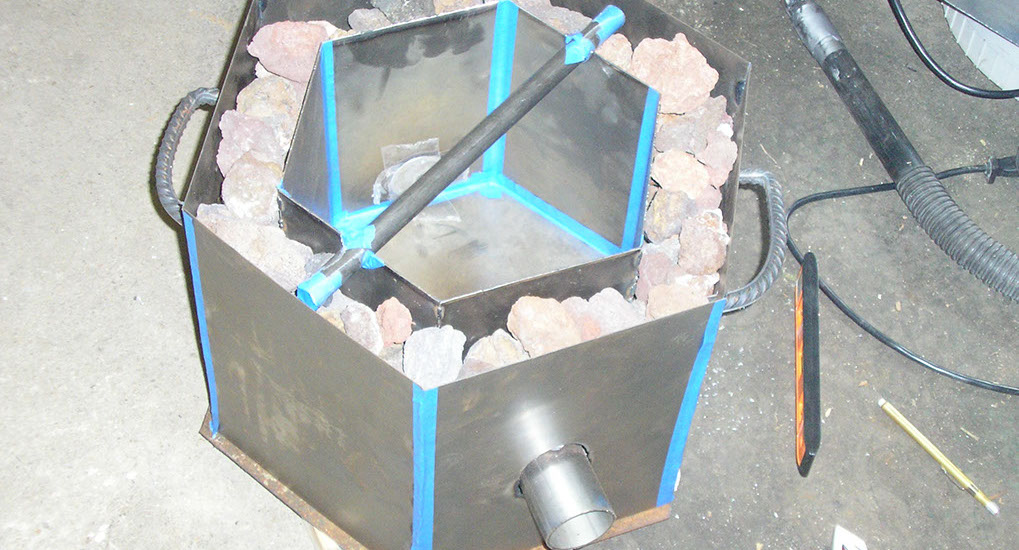
Building the inner cabinet. I wanted a lightweight yet thermally insulative kiln. I recalled how the Romans used pumice in the concrete of the ceiling of the Pantheon, and thought that was a great idea. Filled the base of the kiln with lava rocks.
And then the sides.
Sides filled with lava rocks.
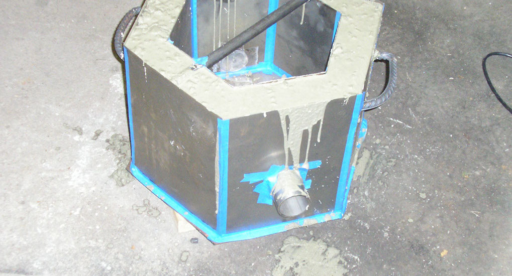
And then filled with concrete. Nice!
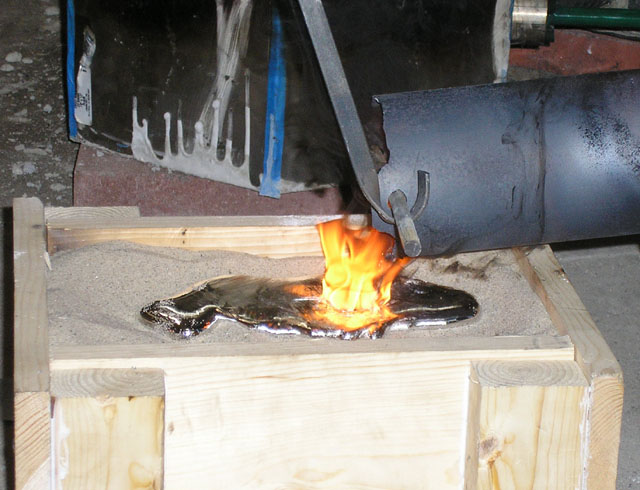
And a test pour.
Next up, is the center stand. This gets deployed when you slow the vehicle down to keep it upright.
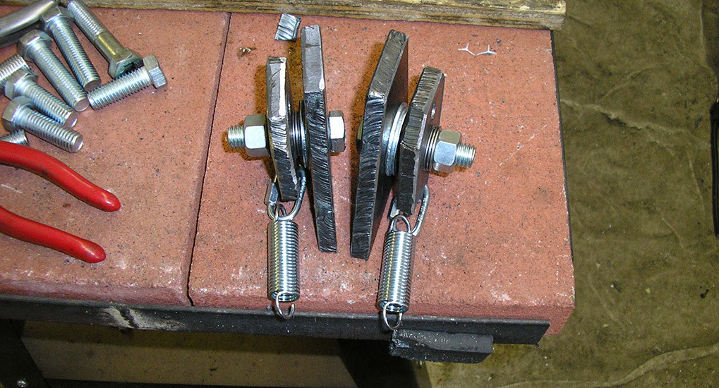
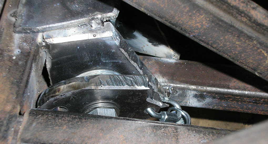
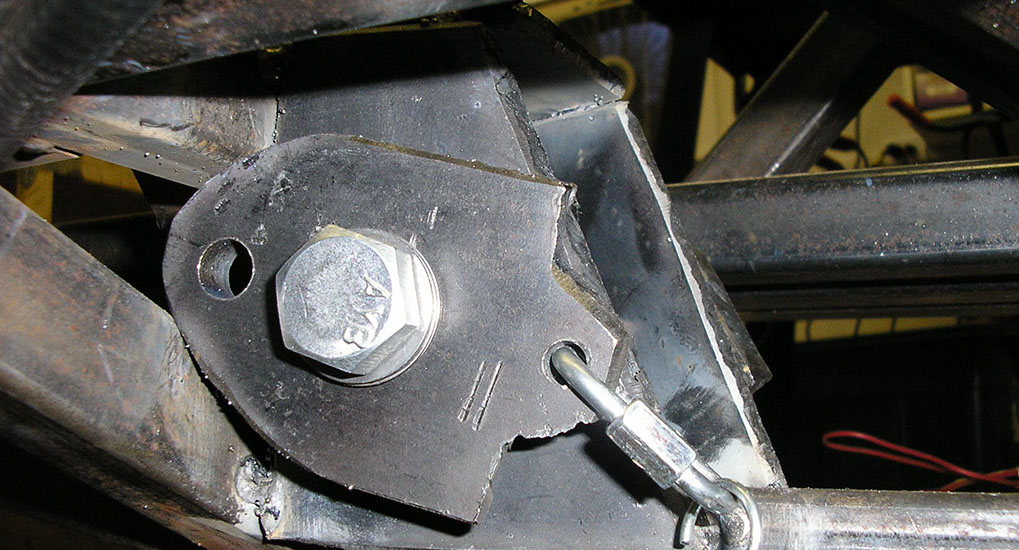
The inner pieces here weld to the frame, the outer rotate when pulled on and will have the caster stands mounted. So they will swing down and touch the ground when you come to a stop.
Tack Welded to the frame
The rotating mechanism.
Another view of it.
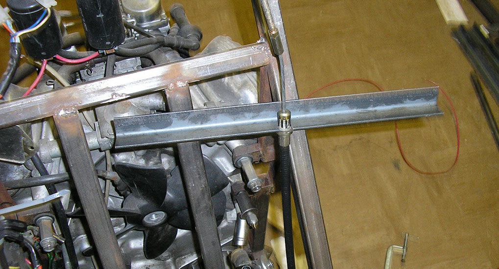
Next up is the mount for the control cable for the center stand.
Here is will the control cable with mount.
Connecting the control cable to the center stand deployment.
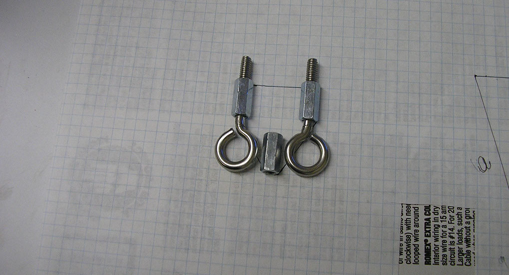
The eyed hooks go to the left and right center stand respectively, while the threaded nut in the middle will attach to the control cable.
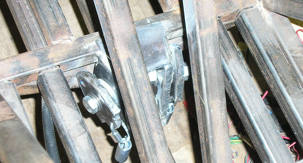
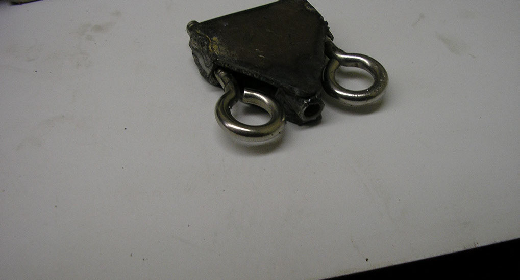
And the whole assembly.
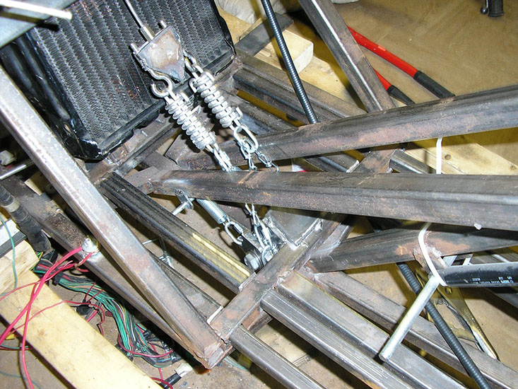
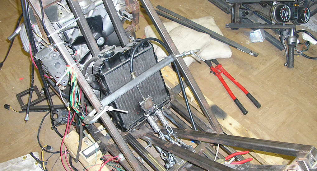
A better view. So obviously the control cable will pull the link up, and that will pull both sides of the center stand up. I added tension springs under the idea that if you are on a slight sideways incline, the side angling down the hill would get slightly more force applied, and be more likely to hold you at an absolute vertical to the ground, instead of a relative vertical.
But what will pull on the control cable? Well, I think later versions will be automatic. But in this version I decided to attach it to the right foot control. On a conventional motorcycle, rotating the right foot engages the rear brake. In an upright bike, you use your quads to hold the bike upright when you come to a stop. But in a recumbent, you end up using the outer (and much weaker) leg muscles. So I decided to have pushing the right foot forward engage the center stand (using the quads) and rotating the right foot engages the brake. In normal riding, you just use the brake in the typical fashion. If it's ice or slippery, deploy the center stand by pushing the right leg forward. In an emergency, your reaction will be to slam your foot forward, and this will deploy both.
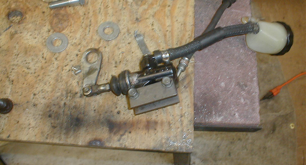
So this is the brake assembly from the Honda 750
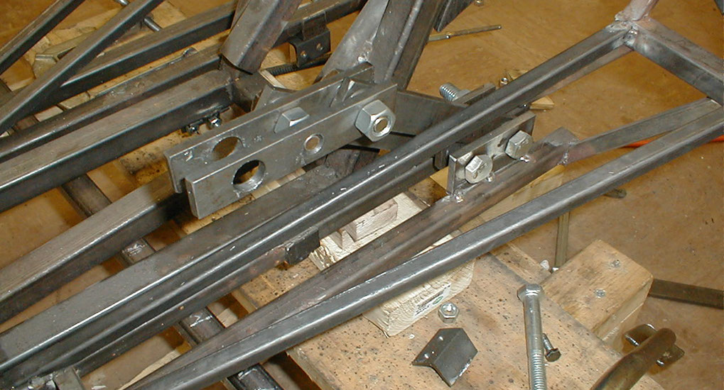
First mounting bracket.
This will be a basic parallel linkage setup. Push it forward and the orientation remains the same.
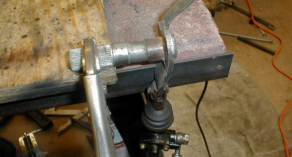
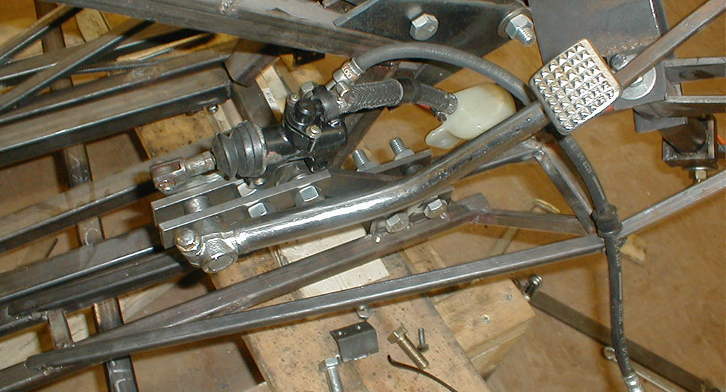
The brake control now mounted to the parallel linkage.
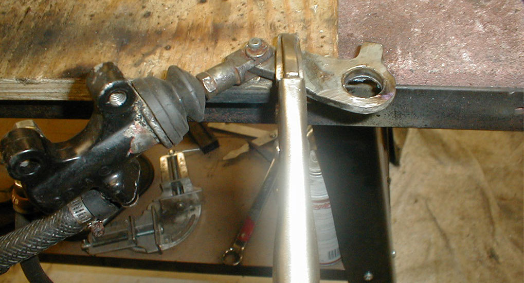
The piston connected now too. So again, rotate right foot = rear brake. Push right foot forward equals center stand. Do both, and you get brake and center stand. That's the theory anyway, testing might make this turn out to be a bad idea. The center stand could be deployed automatically based on speed as well.
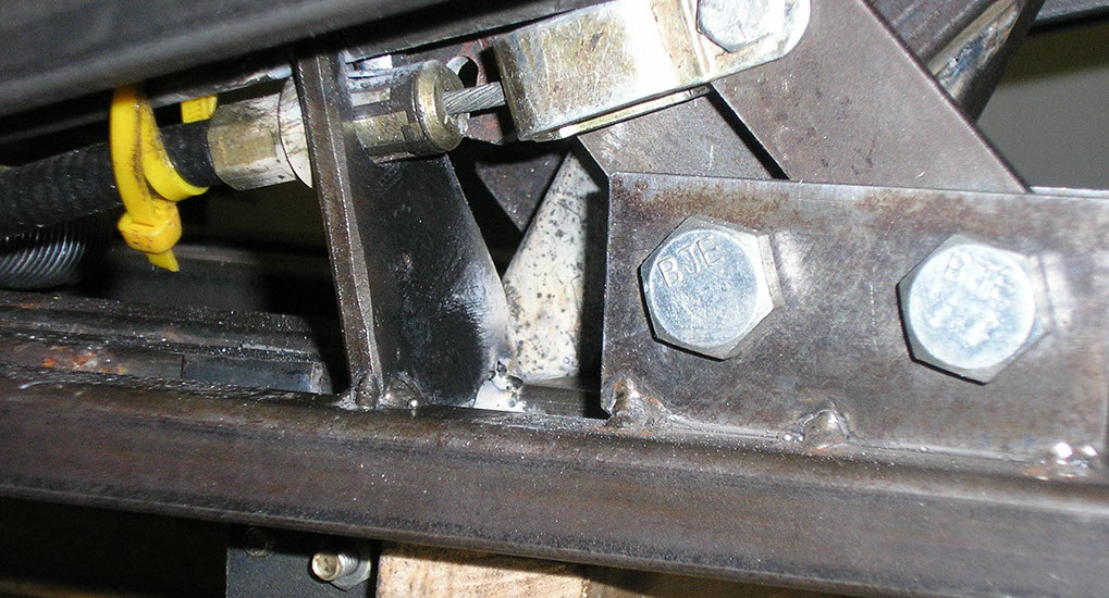
Last is the beefy mount for the control cable where it connects to the right foot control.
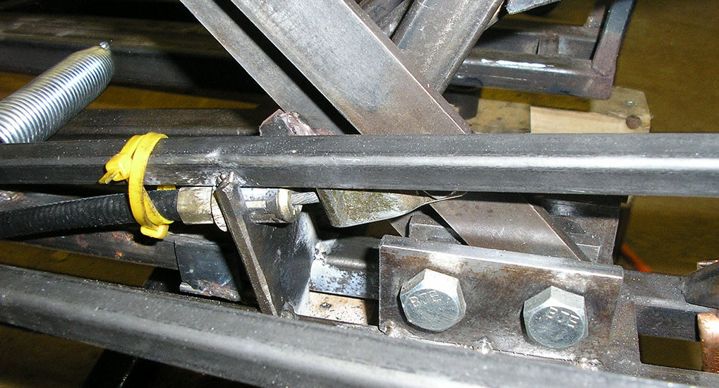
Here it is welded in place. You can now see the control cable mounted to one of the parallel bars as well.
Another view of it.
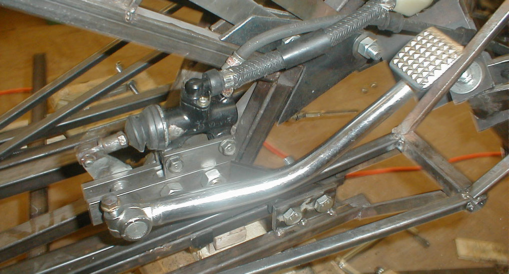
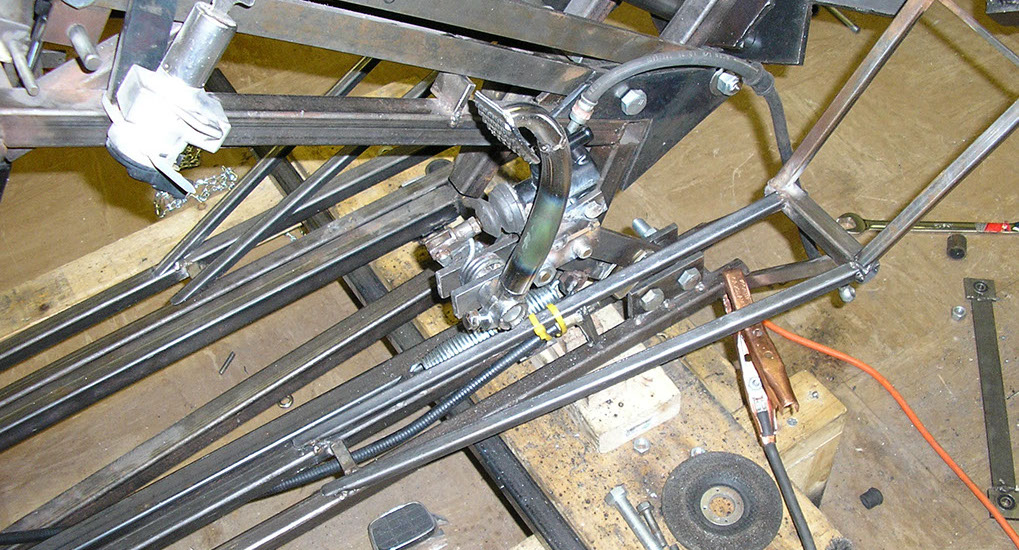
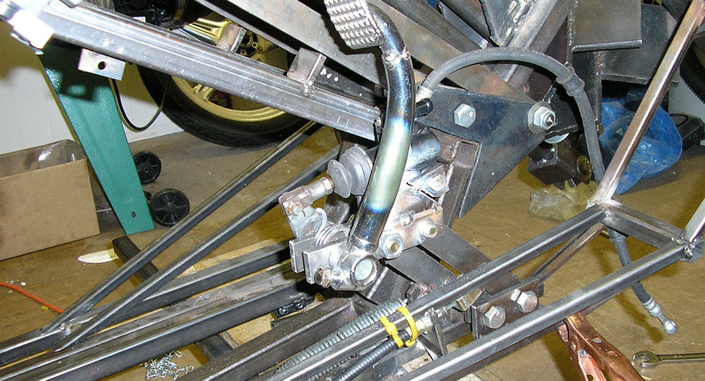
And the full right foot control assembly.
Another view of the right foot control assembly.
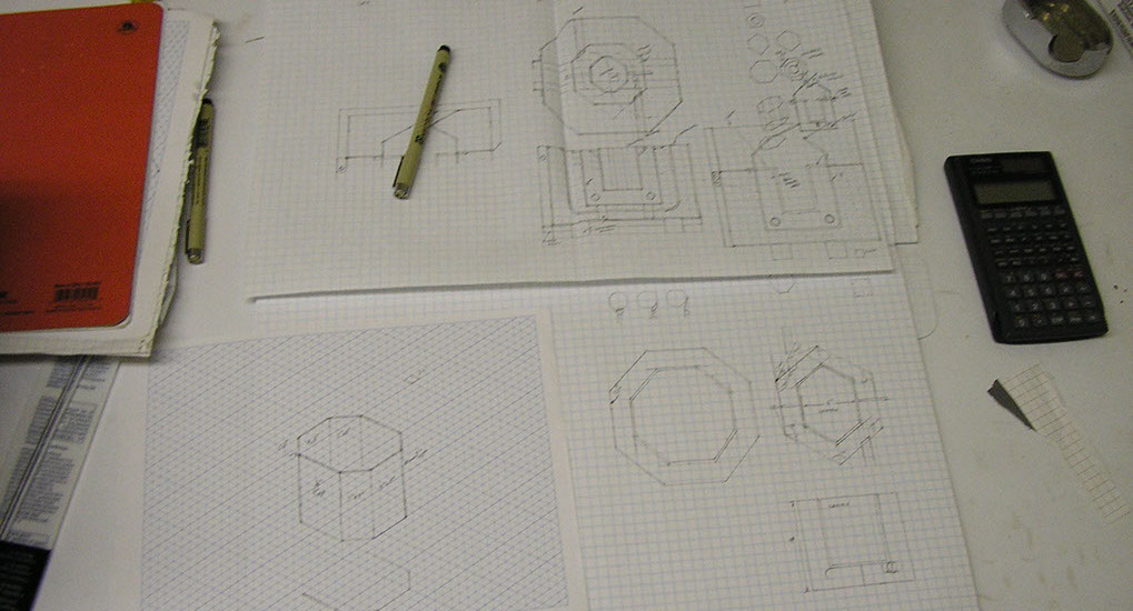
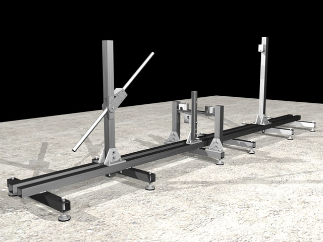
A preliminary design for the frame jig for the next version of the bike.
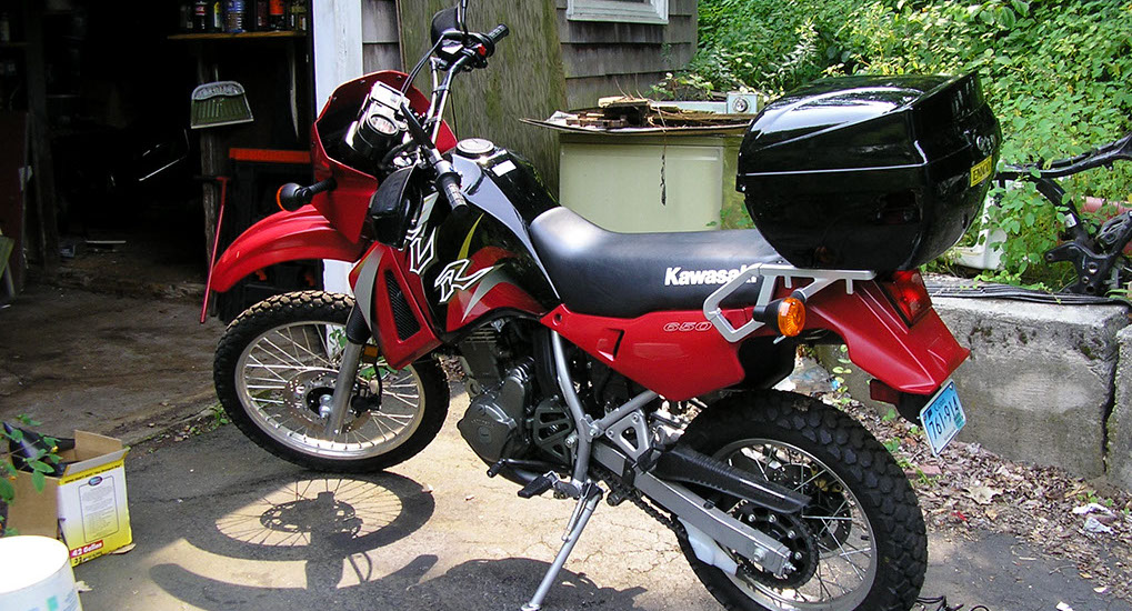
And my new ride, a Kawasaki KLR-650, slightly bigger than the KLX400, which was bigger than the XL250.
1 - 58
<
>
An update to the foot rests, construction of a kiln for aluminum casting, and the addition of a center stand and the right foot controls.
Help bring the fully functional high performance production Akira inspired motorcycle into existence...

Contribute through Amazon affilicate purchases
Donate directly
go to crowdfund for more options
send donations to

