Welcome to Matus1976's Akira Bike Project - Building a fully functional high performance recumbent motorcycle inspired by Kaneda's ride in "Akira"
Update 10




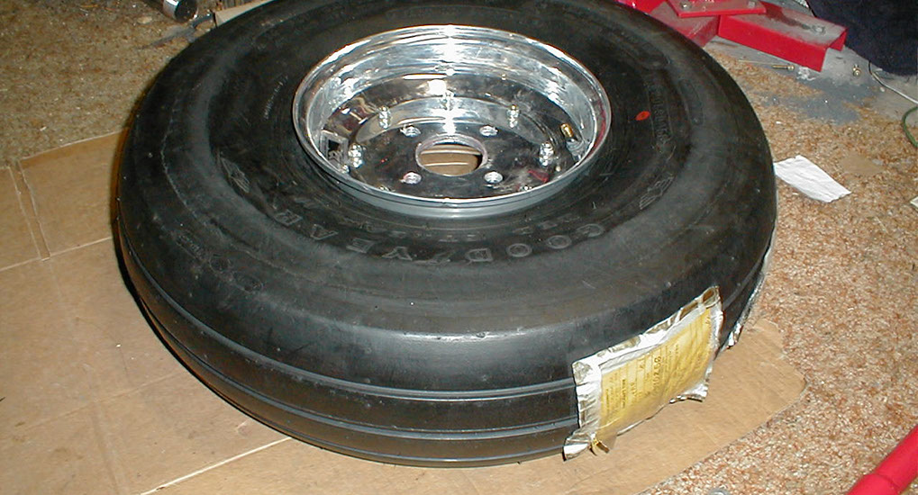
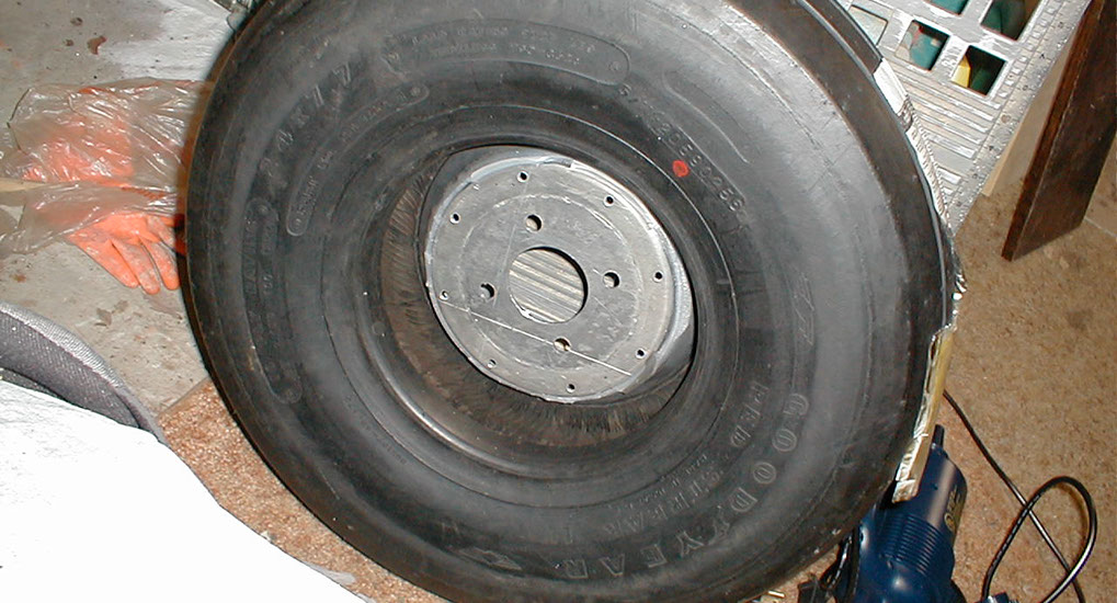
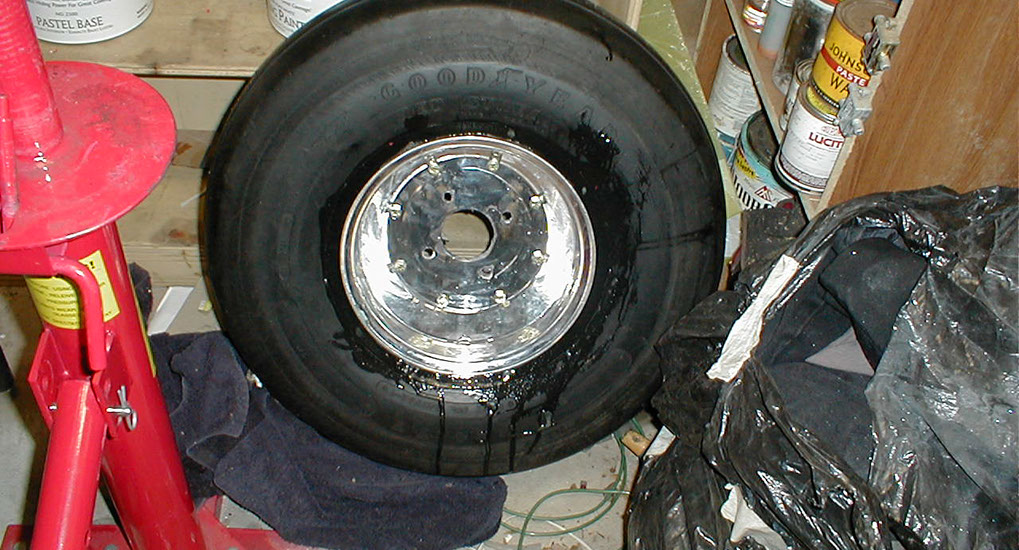
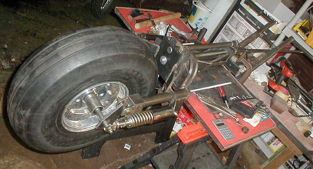
On the the front wheel. This is a 200 mph rated aircraft tire for a large aircraft. Significantly heavier than a conventional motorcycle tire, but I needed larger tires than were currently available for motorcycles. So time to improvise. Aircraft tires are the only other major tires that have rounded profiles. I will cut treads into the tire later. The rim is a split rim for racing dune buggies - or something like that, I can't recall. Don't try this at home.
Aside - the handlebars were a quick easy job.
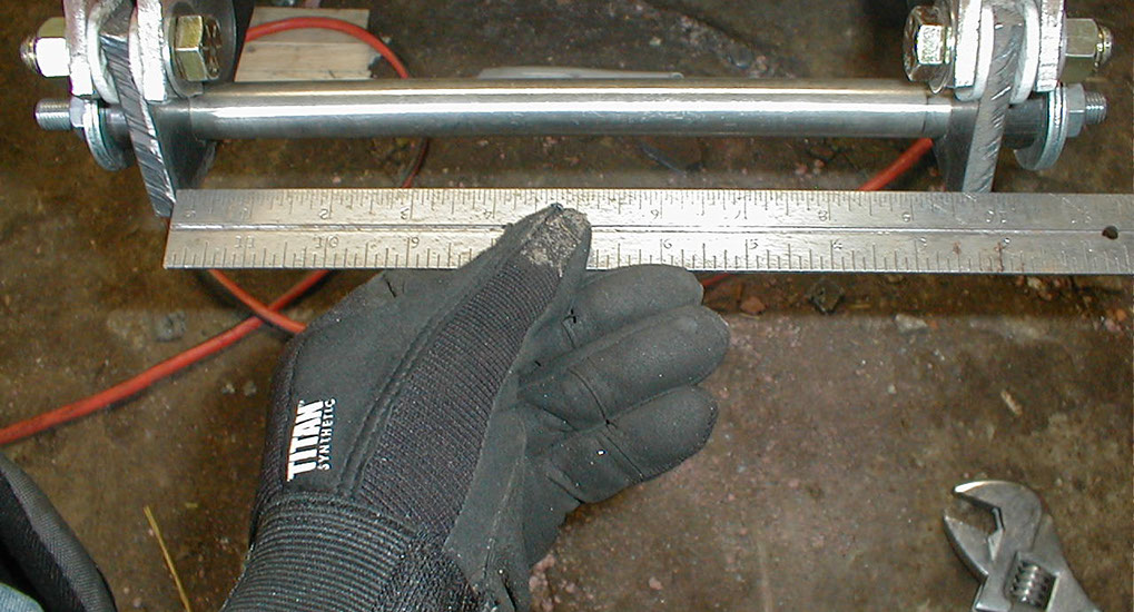
Measuring and preparing to build the front wheel hub.
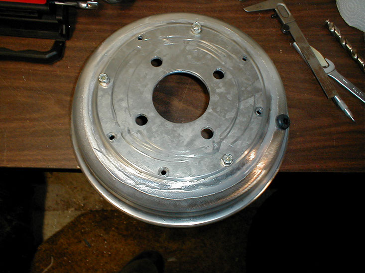
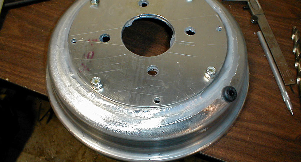
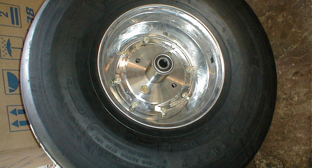
Sealing the hub mount plate to the rim with silicon. Split rims are much easier to mount, and I didn't have the hydraulic tire mounting machine for aircraft tires. But split rims are harder to get an airtight seal with.
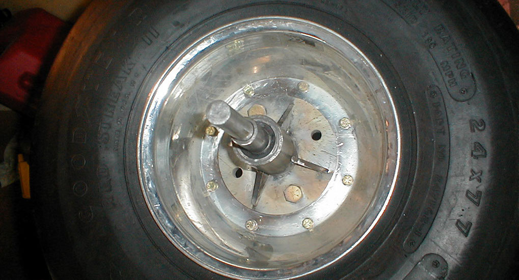
Here the split rim is more obvious, looking through from the other side of the tire...
Soap test to check for leaks. Looks good! Don't try this at home.
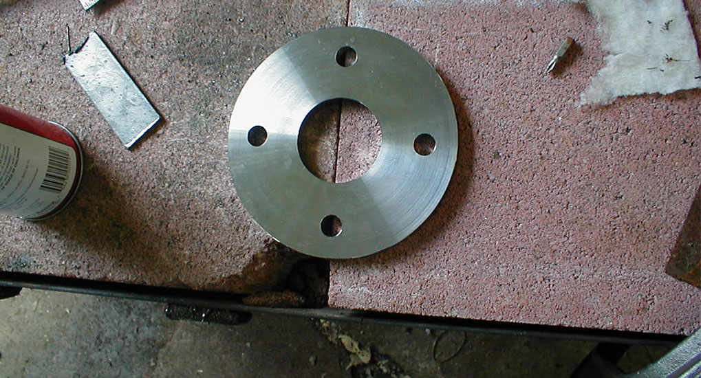
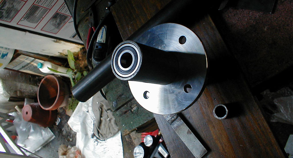
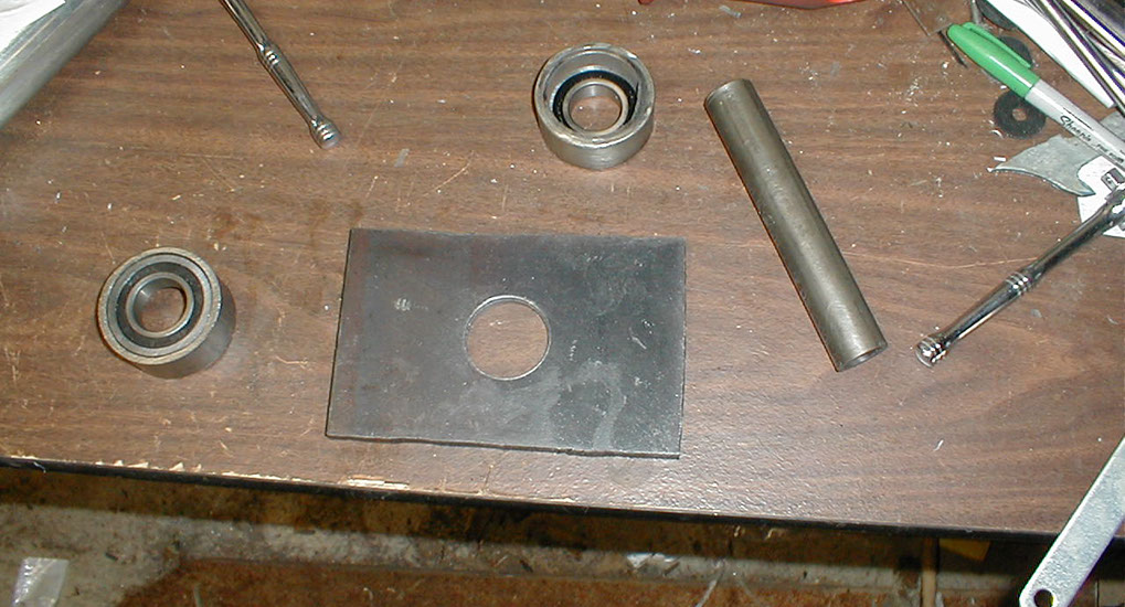
Mounting plate.
We also need a spindle.
Checking distances on the front fork assembly - will this tire even fit?
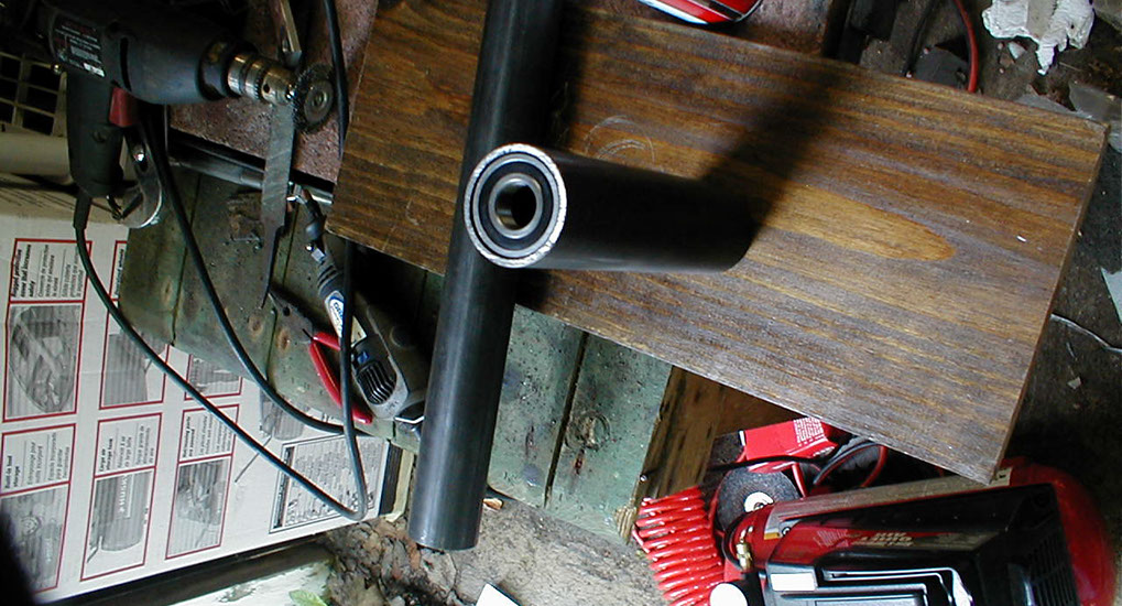
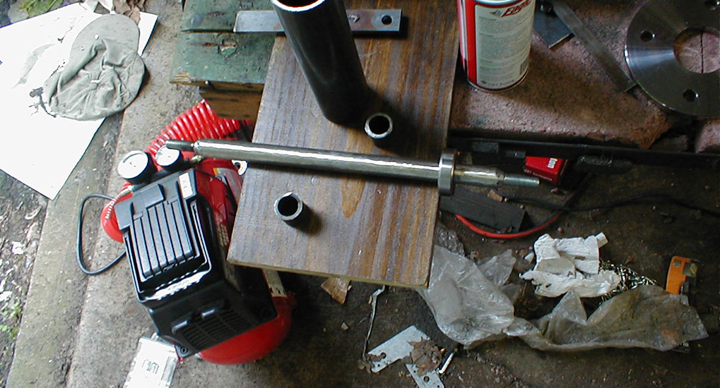
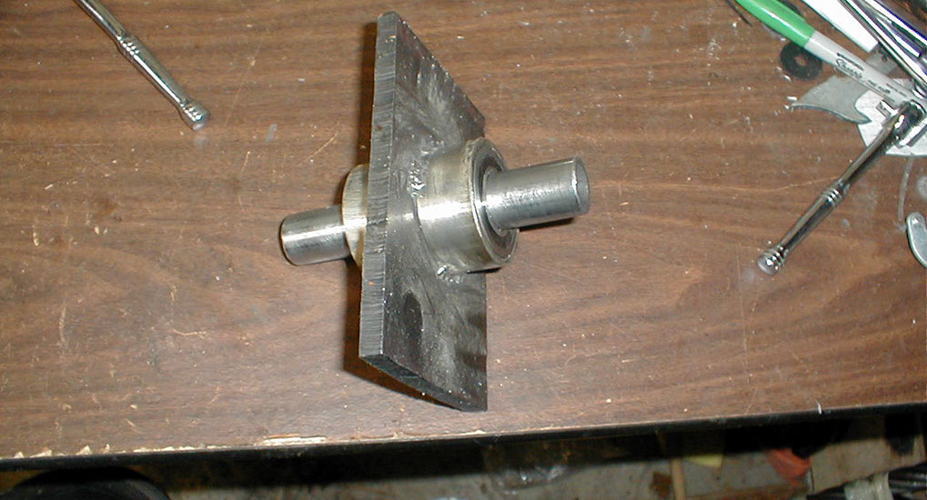
Spindle with the inner mounting cylinder. Basically larger outer diameter cylinder welds to the tire mounting plate, and rides around the spindle with bearings.
Here is the spindle, I have grade 5 fine thread bolts welded to the ands of a 1" steel spindle.
With the mounting plate.
Testing fit. Mounting plate bolted to rim (just two bolts here)
With the inner spindle and spacer.
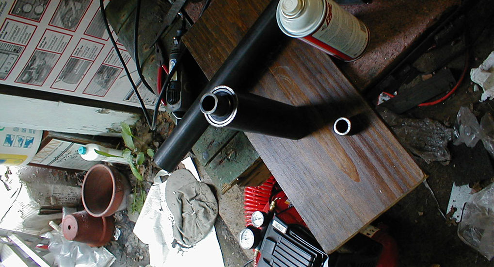
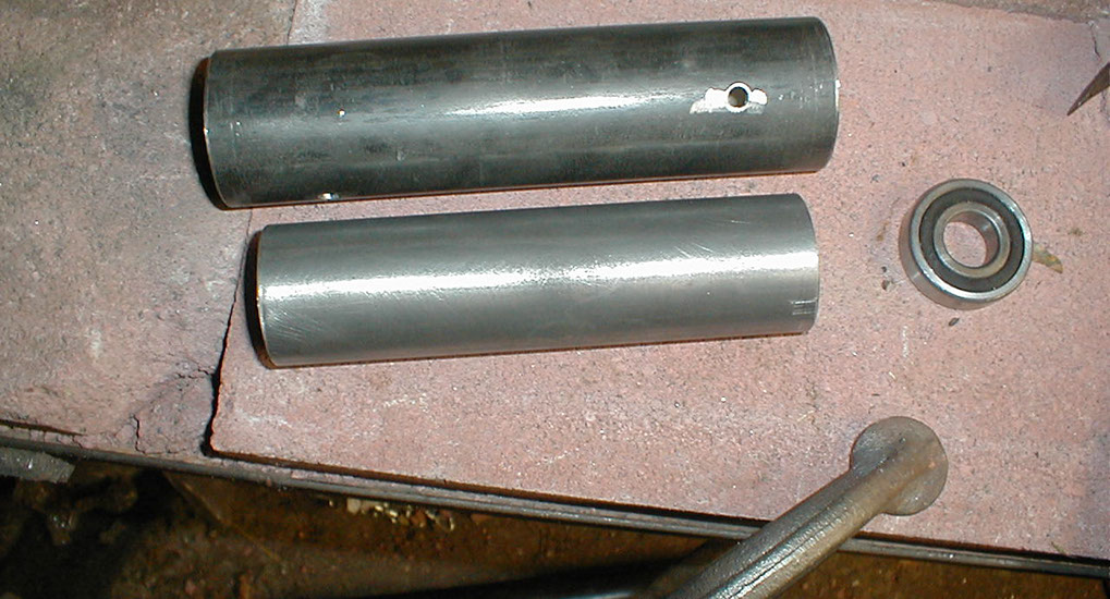
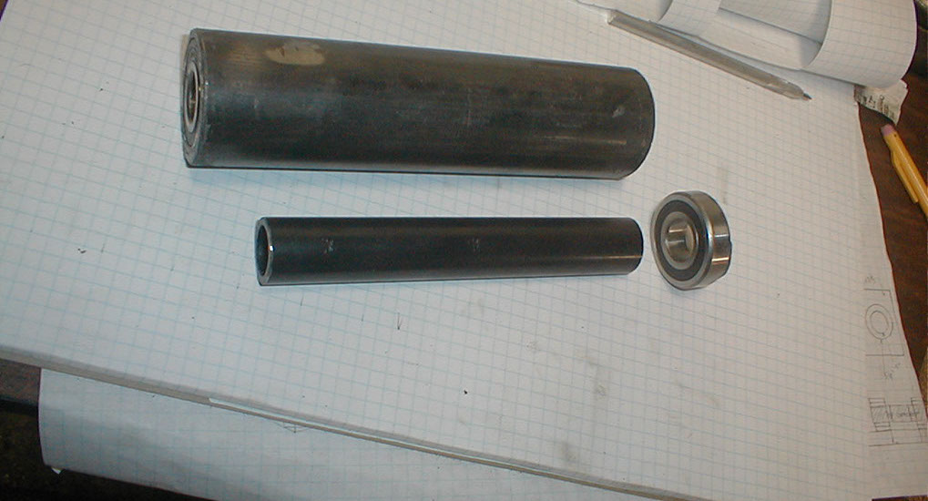
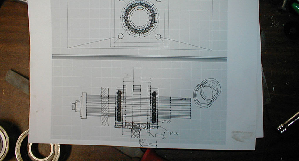
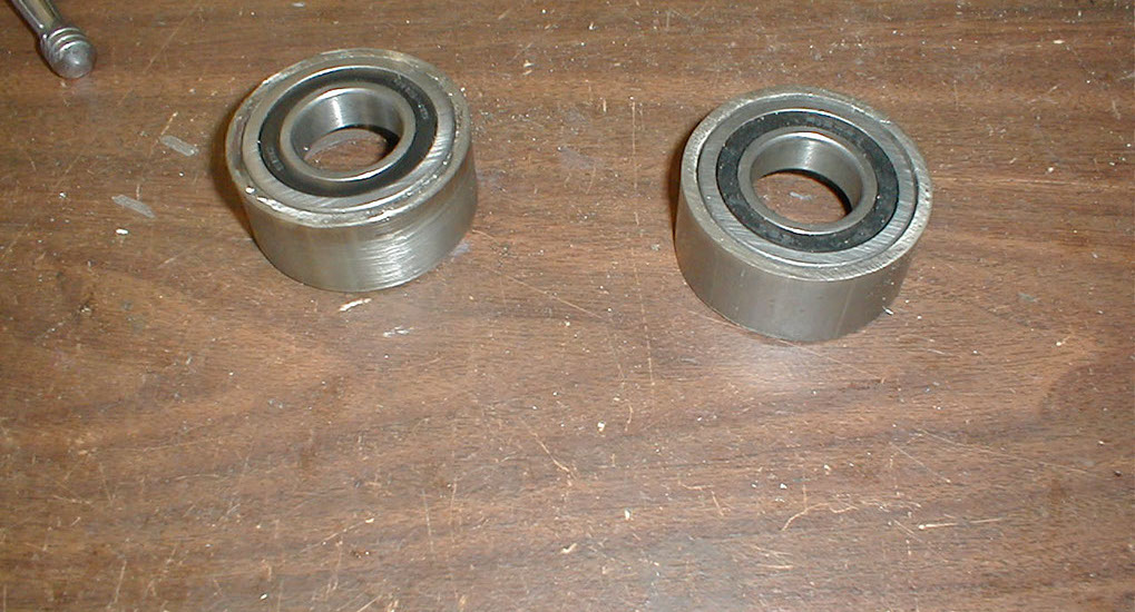
Spindle construction. The outer tube has an inner diameter equaling the outer diameter of the bearing. The smaller cylinder is basically a spacer. With bearings on either end, the whole thing would slide into the larger outer diameter tube.
And then there is an internal spacer. As your radial bearing has an outer race and an inner one, spacers must keep them separated. If, for instance, you had no internal spacer, when you tightened the bolts holding your wheel spindle on, you would compress the inner raceways together, causing serious catastrophe.
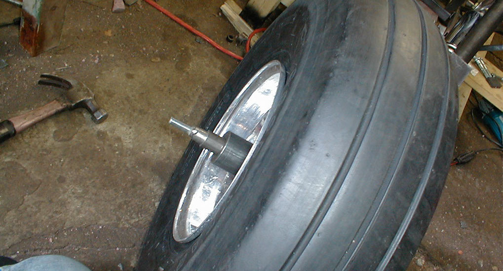
And here is the assembly mounted for testing and fit, although the fork and steering column are upside down to make testing easier.
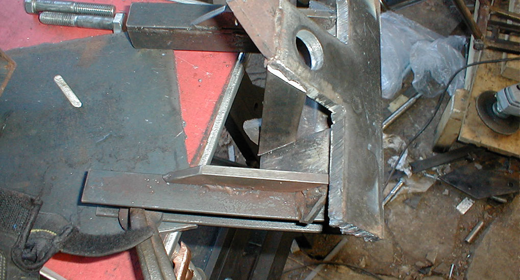
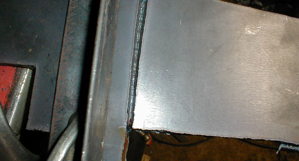
Welding some gussets to the spindle to connect the wheel mounting plate to the actual hub of the wheel.
All together now, not bad!
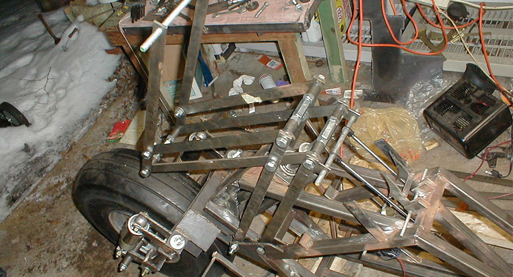
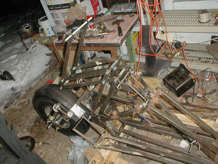
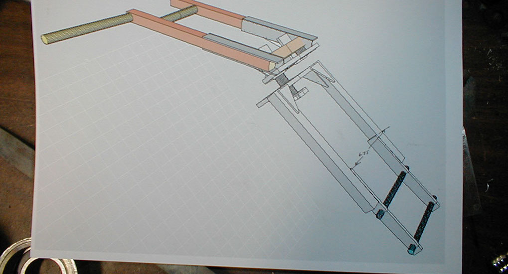
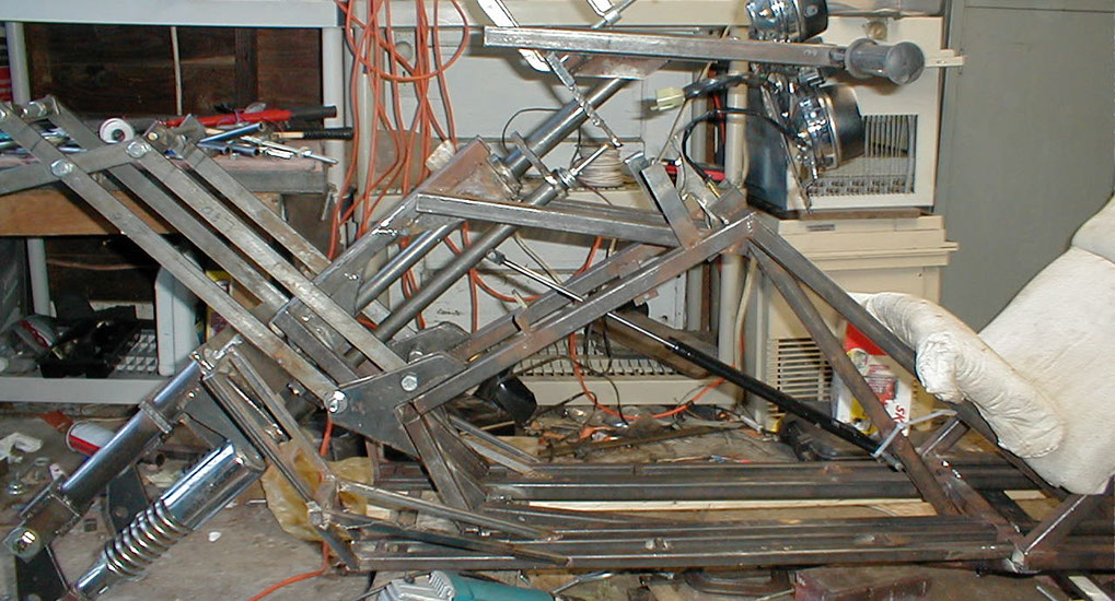
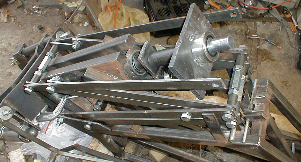
Here again is the virtual pivot point assembly, I added some gas shocks and hooks (to the lower right) pull the assembly down and the hooks grab it. The hooks will have solenoids that pull them off, then the whole assembly rises up.
Another view.
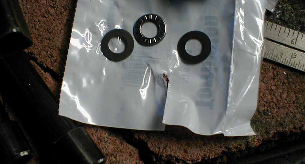
Speaking of the virtual pivot point, based on single 1" x 1/4" cold rolled steel bars, it had too much lateral flexibility. I doubled the bars up and added real thrust bearings.
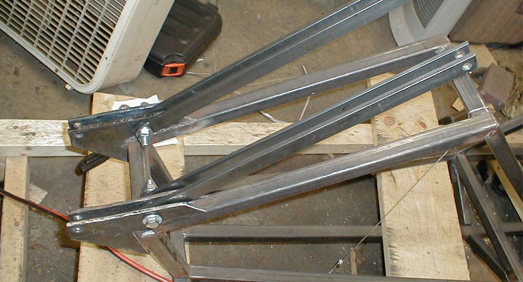
Here you can see the doubling, made additional plates and copies of the same bars. If not stiff enough, I can weld top and bottom pieces to each pair of parallel bars, making a box with protruding side ends.
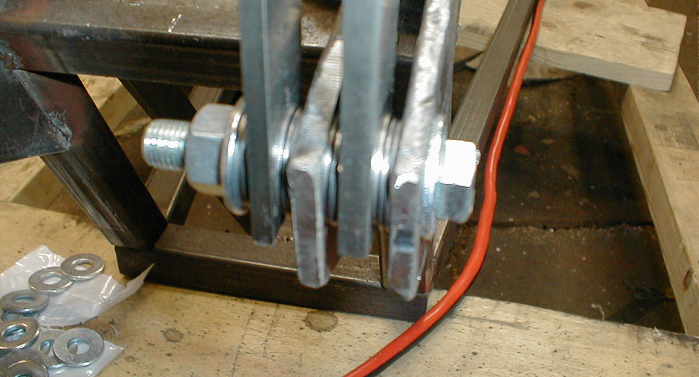
Closer view of the pair of bars and thrust bearings.
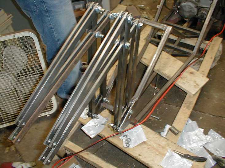
The whole assembly now doubled up.
Around this time, I changed my mind about the front end. Originally the whole steering column would rise up, with a virtual rotation point around the spindle (front axel) so rising this up wouldn't require lifting or lowering the bike at all. Except the actual axis of the front wheel moves based on rider weight. And it's difficult with my equipment to get the locked down steering column super stiff. So I decided to separate the handlebars from the steering column. Now the *handlebars* would rise up around the virtual pivot point, but the steering column would stay put. The only change would be a separate assembly for the handlebars, and some kind of mechanism to lock the handlebars to the steering column when they are lowered. Here's a preview of that.
The handlebars would now need their own mini-steering column. That is what you see here. I will also add high quality aircraft control cables, so even when the handlebars are in the up position, disconnected from the steering column, the control cables will still connect it, to make sure they are always in the same alignment with the actual steering column. Technically you could still steer while the handlebars were up (maybe like a jet -ski) but I won't be trying that.
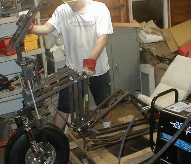
Here you can get a better idea, my brother is checking out the old VPP assembly, note the steering column and handlebars all rise up.
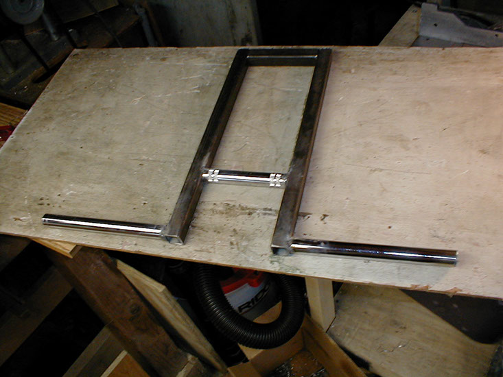
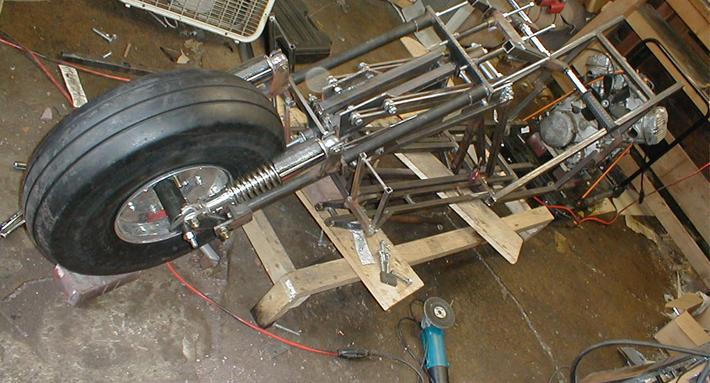
Here you get a better idea on the update. The virtual pivot point bars are fully extended out to the left, but note the steering column is still in the same place. This required only adding two 1" x 1" steel tubes on either side, as the outer width of the column happened to be 2" narrower than the inner width of the upper body of the frame. The locking mechanism is not present here though.
Handlebar mount under construction.
The handlebar's mini steering column ends.
Cutting pieces for the handlebar mount
Handlebar mount pieces
Put together and tack welded
Now it's coming together. Note the upper virtual pivot point bars cradling the sides of the mini steering column for the handlebar mount. Cut, weld, reinforce, good to go.
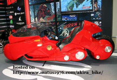
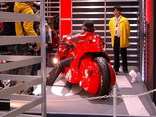
Let me thank everyone who emailed me about the NEO-FUKYOKO project unveiled at the Tokyo Motorcycle show. For those who don't know about it an allegedly functional motorcycle inspired by Kaneda's bike from Akira was presented. As I have been saying to people who have emailed me on the design of an Akira inspired motorcycle, there is more than one way to do it. It is interesting to see an actual Akira inspired bike which has a drivetrain and powerplant.
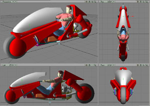
However, I have many objections to the design used for the NEO-FUKUOKO project. As you can see from the picture above, one objection would be size. Clearly the riders head sticks up way over the 'head rest' of the bike.
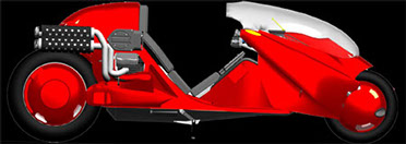
As you can see from my earlier test renderings of the finished bike, the headrest clearly rises above the head of the vehicle operator. From what I understand they are still undecided on when / if it will be sold and how much it will cost. Additionally, the engine is in the front, requiring some 8' of chain spanned over three separate sprocket pairs to get to the rear wheel. The front cowling does not appear to raise / lower either.
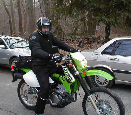
My new ride, Kawaski KLX-400, upgraded from the HondaXL250. I started on a small bike and progressively increased the size, this is the safest way to learn to ride (aside from growing up doing off-road riding)
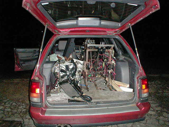
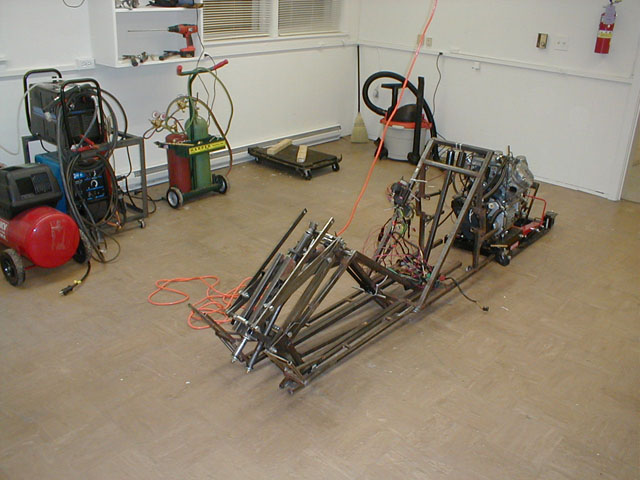
Bad luck struck around this time, I got laid off from my nice Pfizer IT job. Big cut-backs at the company, and not alot of other big IT employers in South Eastern CT. I regrouped, rented my house to my parents, moved in with my brother, and rented a small workshop. Amazingly I was able to fit my disassembled bike into the back of my Subaru. Nice!
A dozen trips later and I'm getting moved into the new shop.
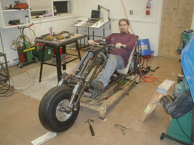
Here is the current progress, me on the bike. Looking good.
Progress will be slow for some time as I'm getting some parts custom made, and, well, I got laid off.
1 - 42
<
>
Updates to the Virtual Pivot Point assembly (seperating it from the steering column), constructing the front wheel hub, handlebar mount, and laid off - moving to a new shop.
Help bring the fully functional high performance production Akira inspired motorcycle into existence...

Contribute through Amazon affilicate purchases
Donate directly
go to crowdfund for more options
send donations to

