Welcome to Matus1976's Akira Bike Project - Building a fully functional high performance recumbent motorcycle inspired by Kaneda's ride in "Akira"
Update 22
As 2014 comes to an end, this update relates some design and re-enforcement work done on the forks, some work on the steering colum, and a move to a new workshop


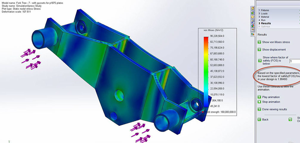
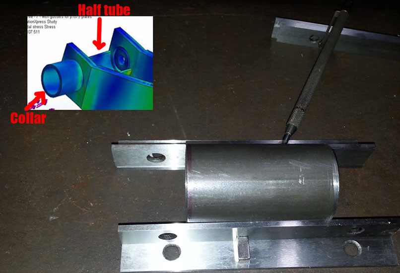
The first major part of the update is to re-enforce the front fork, which while being sufficient for a rolling chassis lacks the strength and stiffness necessary for riding conditions. After about 20 revisions that were consistent with my existing design and assembly requirements as well as having minimum modifications, the addition of the half tubes and collars as well as the two vertical plates in the middle brought the factor of safety up to 1.99. This is with a 1,000 lb load on the fork tubes, which is roughly what would be experienced when slamming on the brakes. Under maximum deceleration the force on road vehicle is roughly the weight.
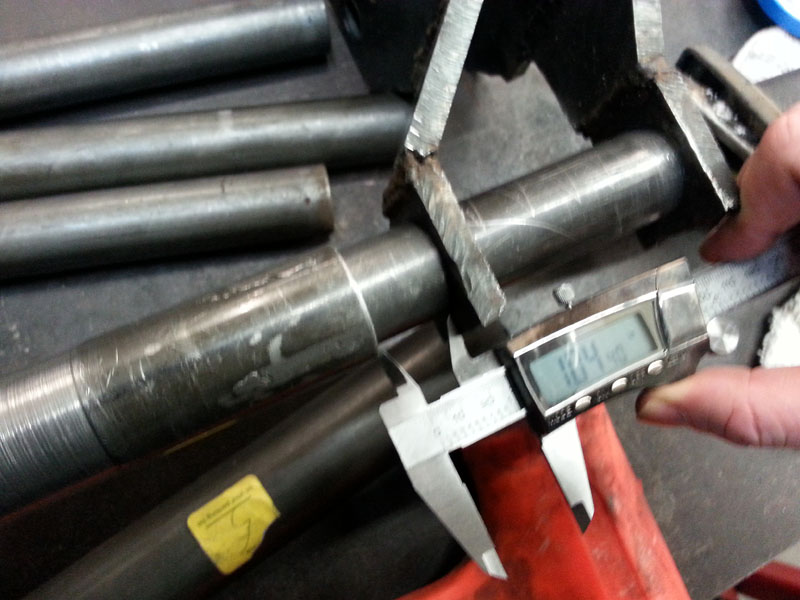
First was to close the gab between the outer fork tube (the larger diameter tube on the left of the calipers) and the lower tree of the fork (at the right side of the caliper) The gap came from some design modifications earlier. The gap is 1.04" ... onto the lathe.
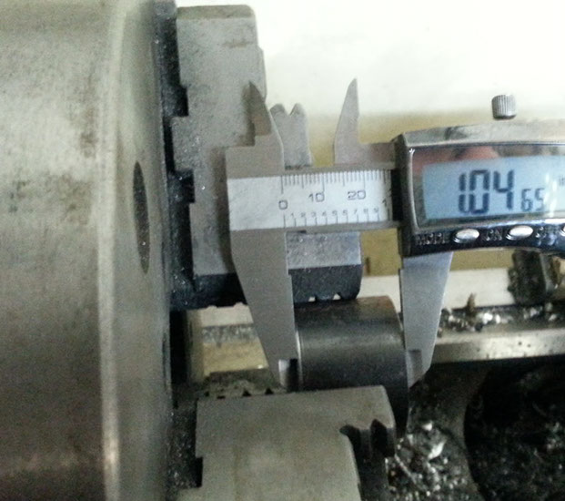
After cutting the tube on the chop saw I ran it on the lathe to square the ends. After some time the length is good, 1.04" One was made for each side
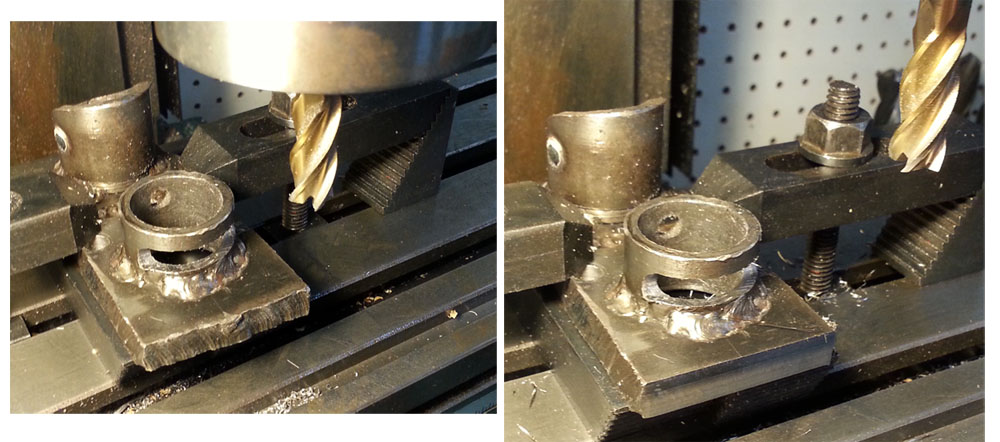
On to the next piece, the half tube. This will get welded between the upper and lower T of the fork, and is a larger diameter than the existing upper suspension mount. Here I am marking the source tube using some parallel bars along the midline for cutting in half.
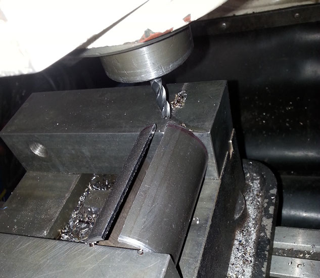
Slicing the source tube in half with a milling machine, nice clean square straight cut.
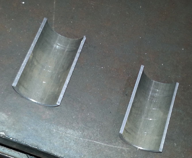
The two tube halves after cutting
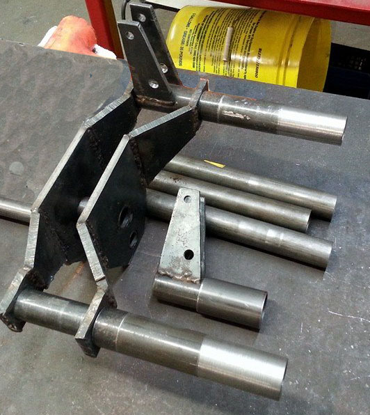
This image shows how the tube halves will cradle the suspension mounts
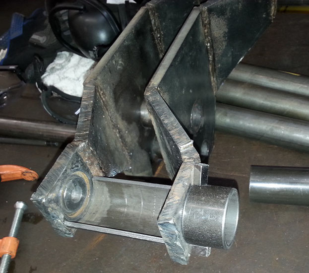
Here is the collar and the half tube temporarily held onto the fork with magnets, showing where they will get welded on
Here are both collars and half tubes on the fork
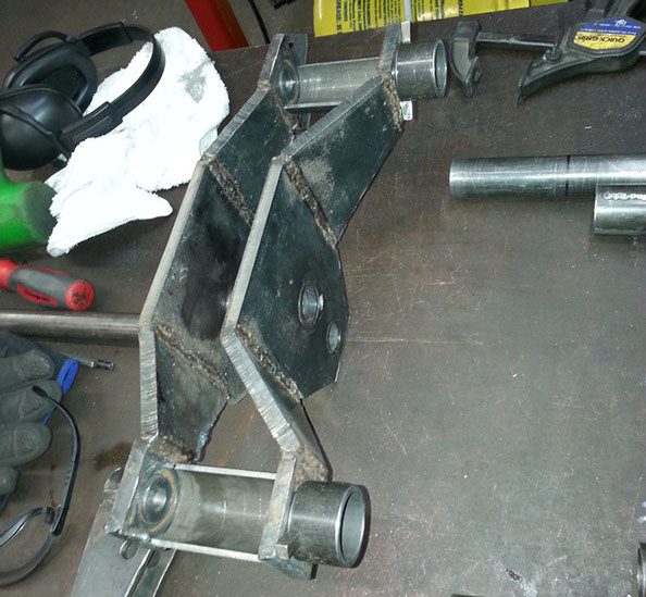
This image shows how it all goes together, note the upper suspension mount on the left side of the fork is in place.
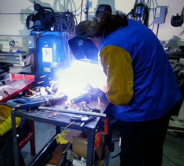
I also did some repair and re-enforcement welds on the fork trees, but have not welded the collar and half tubes in yet, I'm waiting on getting the electrical for my TIG welder hooked up for that.
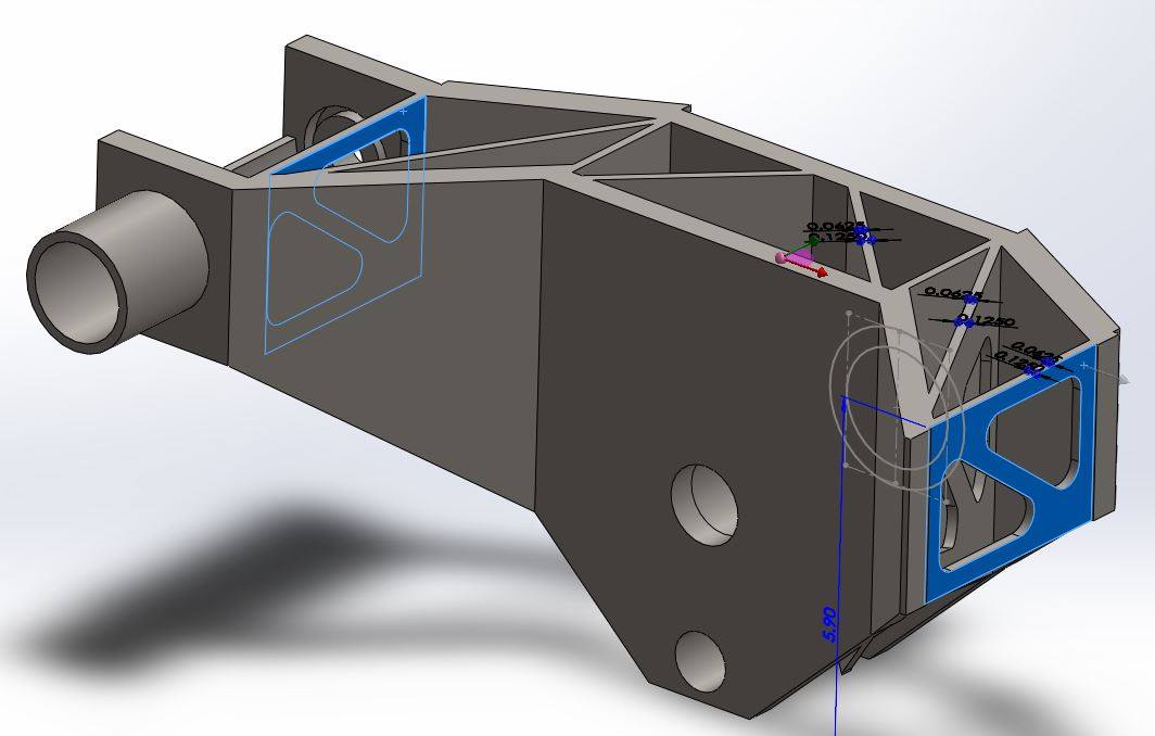
After some additional rounds of modeling and simulations for the fork, I added triangulated gussets. These added about 3lb of weight, but increased the safety factor from 2 to 4.5. I later cut triangles out of the plates to drop it to a FOS of about 4 but dropped the additional weight down to about 1lb.
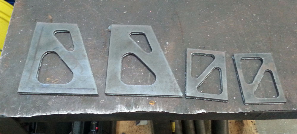
Cutting the triangular holes out retains most of the strength and stiffness but removes a large portion of the weight. Ideally the thick plates that make up the fork itself could have triangulated holes removed, but I don't feel it is necessary for the prototype. Designs can be perpetually refined but at some point you must stop and say "It's good enough" or you'll never finish anything. Next, cutting the plates.
How to cut the plates? Well, they need to be pretty accurate, really more accurate than I can do by hand with a plasma cutter. If I cut them by hand, I would need to spend quite alot of time grinding to get them right. 'If only I had a CNC plasma cutter' I thought. Wait. I have a plasma cutter, AND a CNC... So the next two days I spent modifying our CNC to move the plasma torch around. It worked great! I ended up bolting a 6 foot arm to the 4th and 5th axis trunnion protruding out the CNC over my work bench. Check out the video of the process
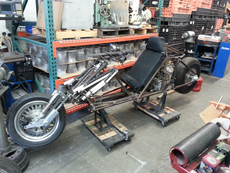
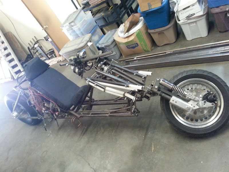
After some changes at Crazy Horse motorcycles, I decided it was best to move to a new shop, and it was quite crowded in there. I found a great deal on a shop just a couple buildings over, which made the move quite easy. Here is the Akira Bike getting ready to be moved.
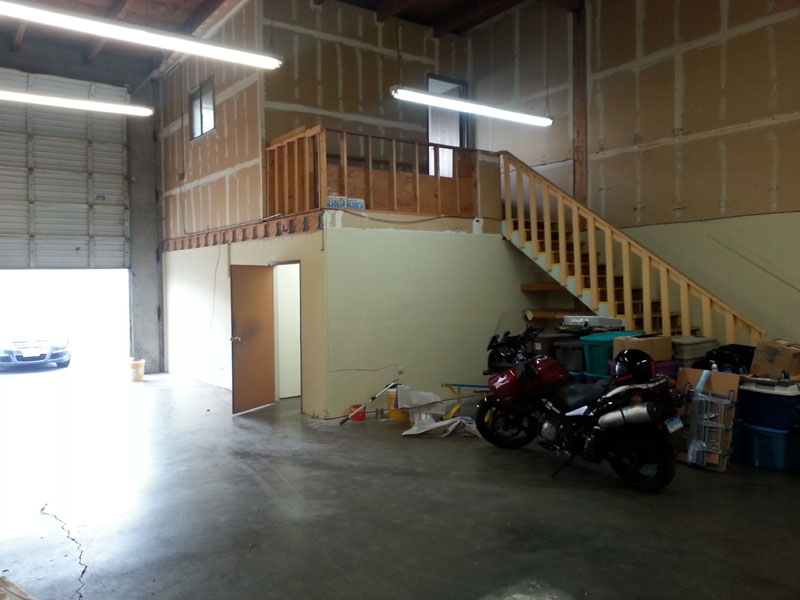
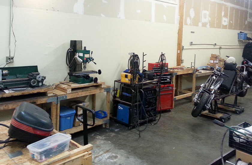
The new workshop, I've only moved a few things so far, including the V-Strom I ride until my bike project is done. I'm sick of moving my shop, but hopefully this is the last time. This is the 7th time I've moved my workshop - thanks to layoffs, house sales, and a cross country move. It has been an interesting struggle with many ups and downs. Just trying to maintain a functional workshop is a large struggle of this project - but some good things are in place now. A decent shop, great tools, a close relationship with Crazy Horse with a ready supply of their excellent V-Plus motor.
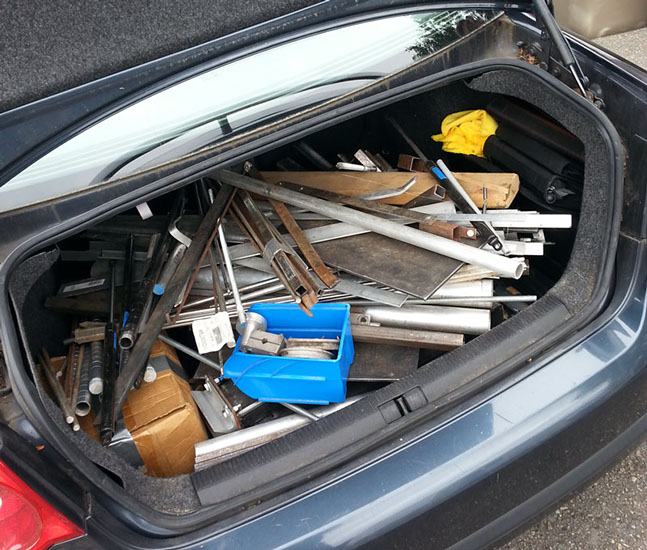
Loading up my Jetta with all the metal and some extra parts
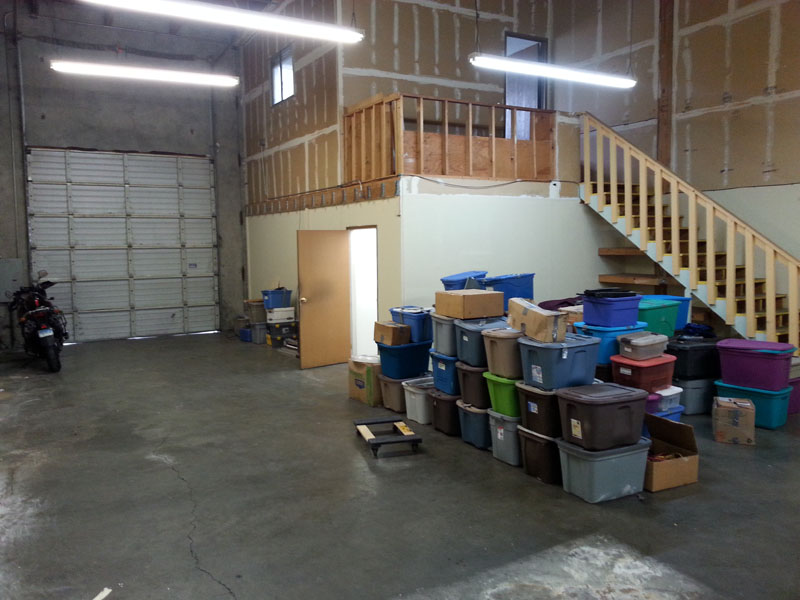
More things moved into the shop, these handy storage containers have been with me through all 7 moves! (with some attrition...) The shop is 1600 sf with 25' ceiling, a 10x15 area is sectioned office for a small office with a small kitchen and bathroom. If you want to see a fully functional high performance motorcycle inspired by Kaneda's ride, please contribute!
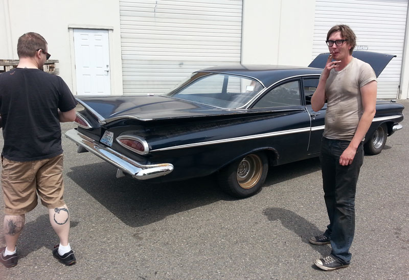
Two of my coworkers at my new job helped me move, here we are in back of the old shop with Matt's 59 Bel Aire. Many thanks to these guys for helping me move, even after I'd only known them for a few months.
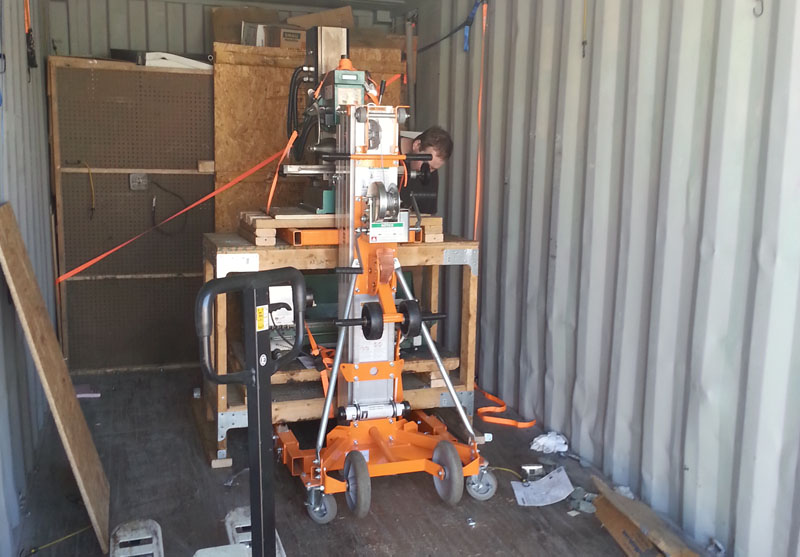
The two hardest things to move were the milling machine and lathe, here we are moving the milling machine out of the container. The orange thing is a hand cranked lift, like a pallet jack, except it can go 16' in the air, although in this case it only needs to go 3' to get under the milling machine. My mill and lathe had not left my storage container since I moved to Washington, as I had access to a larger mill and lathe at Crazy Horse.
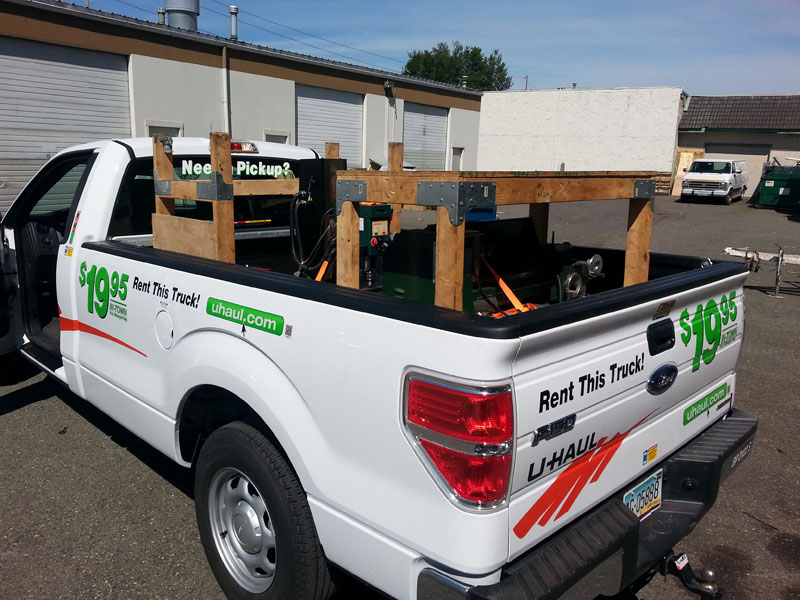
One of 8 total loads to the shop. Here the mill and lathe are in the back of the pickup, along with their respective workbenches.
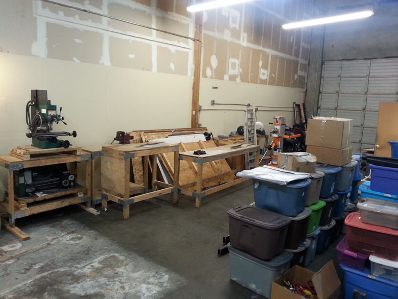
The mill and lathe unpacked and at the new shop. Obviously the lathe is not going to stay down there
Next was to move the bike, with the help of a friend, we walked it over to the new shop. Check out the video of the move
At home in the new shop, the Akira Bike project prototype is back on it's work stands. Starting to set the shop up here.
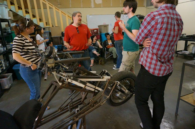
Shortly after that I had a workshop warming party / birthday party. Here I am explaining some of the details of the design to some friends.
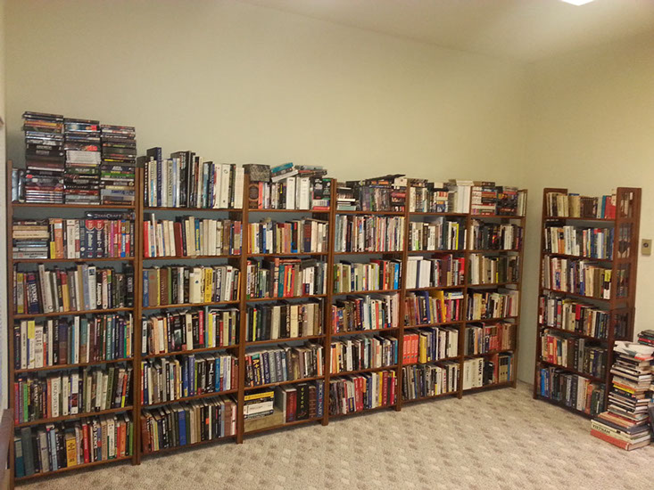
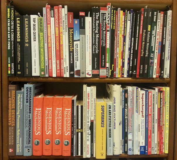
Along with moving into a new shop, I finally was able to unpack my books. Here is most of my library, the collection of a bibliophile / entrepreneur / inventor.
And here specifically are my motorcycle and design related books. The most valuable have certainly been the top shelf middle three, Tony Foale's "Motorcycle Handling and Chassis Design" and John Bradley's two books "The Racing Motorcycle - A technical guide for constructors" vol1 and vol2. Now back to the build...
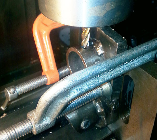
A major concern I have is the rigidity of the steering column. Because of the legacy of the design history, I went with a different configuration for my steering setup than the convention parallel bar fork tubes. This piece clamped into my milling machine is where the steering column meets the handlebar holders. Here I am enlarging the small hole into a larger groove, this is where I will weld the mount to the actual steering column. Beyond that, an internal mechanism will provide additional rigidity.
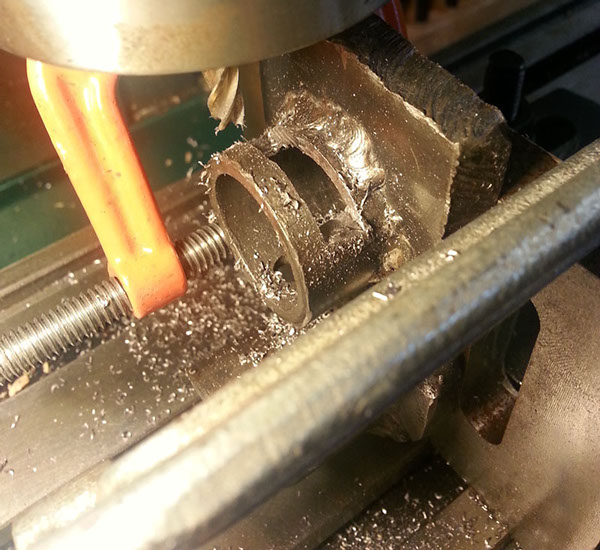
Here the groove is machined in. During normal steering conditions, there is no real need for concern, but if the bike develops a high speed wobble, significant forces get applied to the steering system, as essentially some of the velocity of the vehicle is converted into rapidly swinging the steering back and forth, it is a scary and dangerous effect. Steering dampers significantly reduce this effect though. Dampers typically work by pushing fluid through a small orifice, the resistance to this flow increases with the square of the fluid velocity, so the faster your handlebars swing back and forth, the more the dampers slow the swinging.
Here is the part with the groove machined in. I put some white foam inside just so you could more clearly see the groove. I'm not sure if I'm happy with this overall part, I'll be doing some stress analysis on it in simulations later.
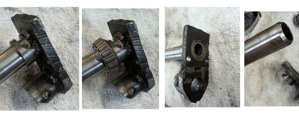
Here, on the left we see the steering column inserted into the handlebar mount. The next image shows where the steering column bearing sits. This is why I can not weld that side of the mount to the tube. However on the other side, in the 3rd image, you see how the steering column passes through to the other side. On this side, I will also weld it. In the fourth image, I beveled the end of the steering column tube to better facilitate welding it.
Another quick modification, originally these parts were cut with a plasma torch, though the top of the steering column / handlebar mount won't be connected to anything, I like to put an angle measuring tool on there to double check the steering angle clearance. Since it was rough and uneven, that didn't work well, so I quickly milled the top flat and square to the centers of the tubes which mount to the steering column.
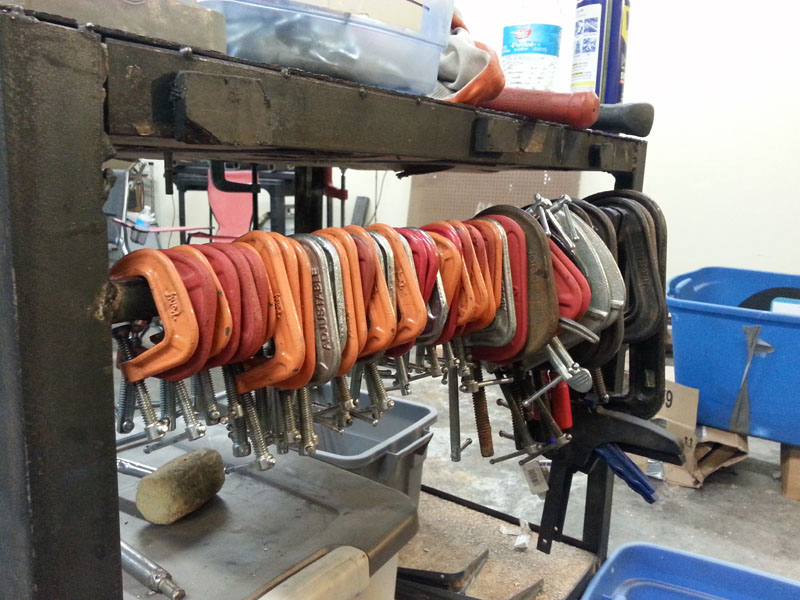
Welders need many C-Clamps. This is only part of my collection!
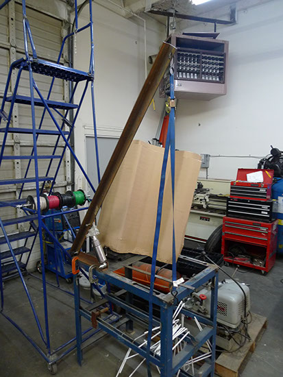
A quick testing rig to measure how far the suspension will compress, it's at the hinge of a 6' steel bar, along with a tether ratchet to hold it under compression while I measured it
Here is some awesome fan art from artist Maxim_fleury over at http://www.zbrushcentral.com/showthread.php?90831-Akira
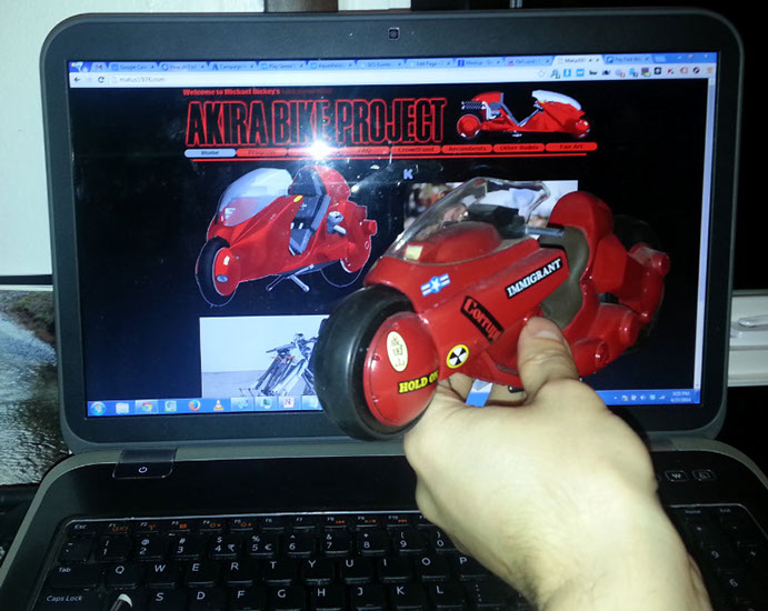
Fan of the project Carl sent this image in of his Kaneda's bike in front of my project web site. I love this picture! If you have one of the models and Kaneda's ride, take a picture like this and send it in.
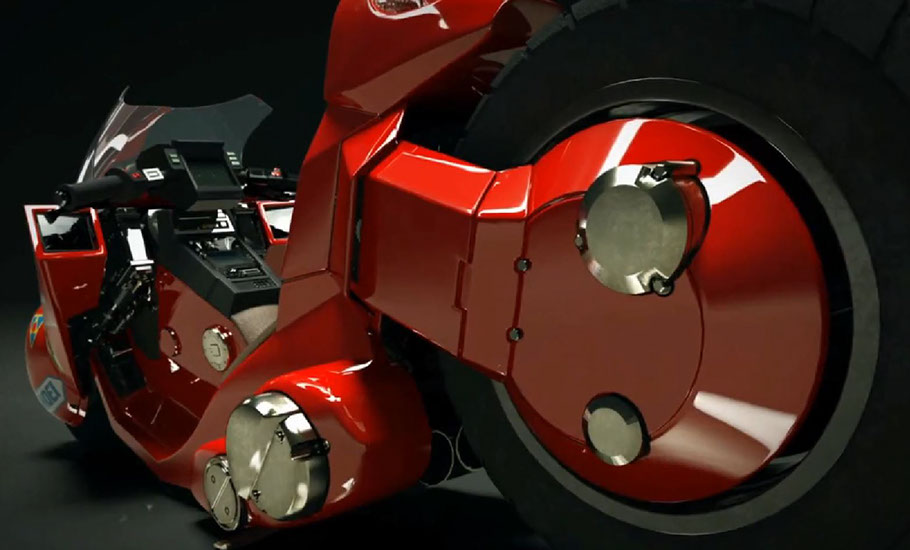
Check out this absolutely magnificent video of a 3D Kaneda's bike by Highend Render https://www.facebook.com/video.php?v=1438301976443001
I will, of course, be doing a similar animation detailing my design.
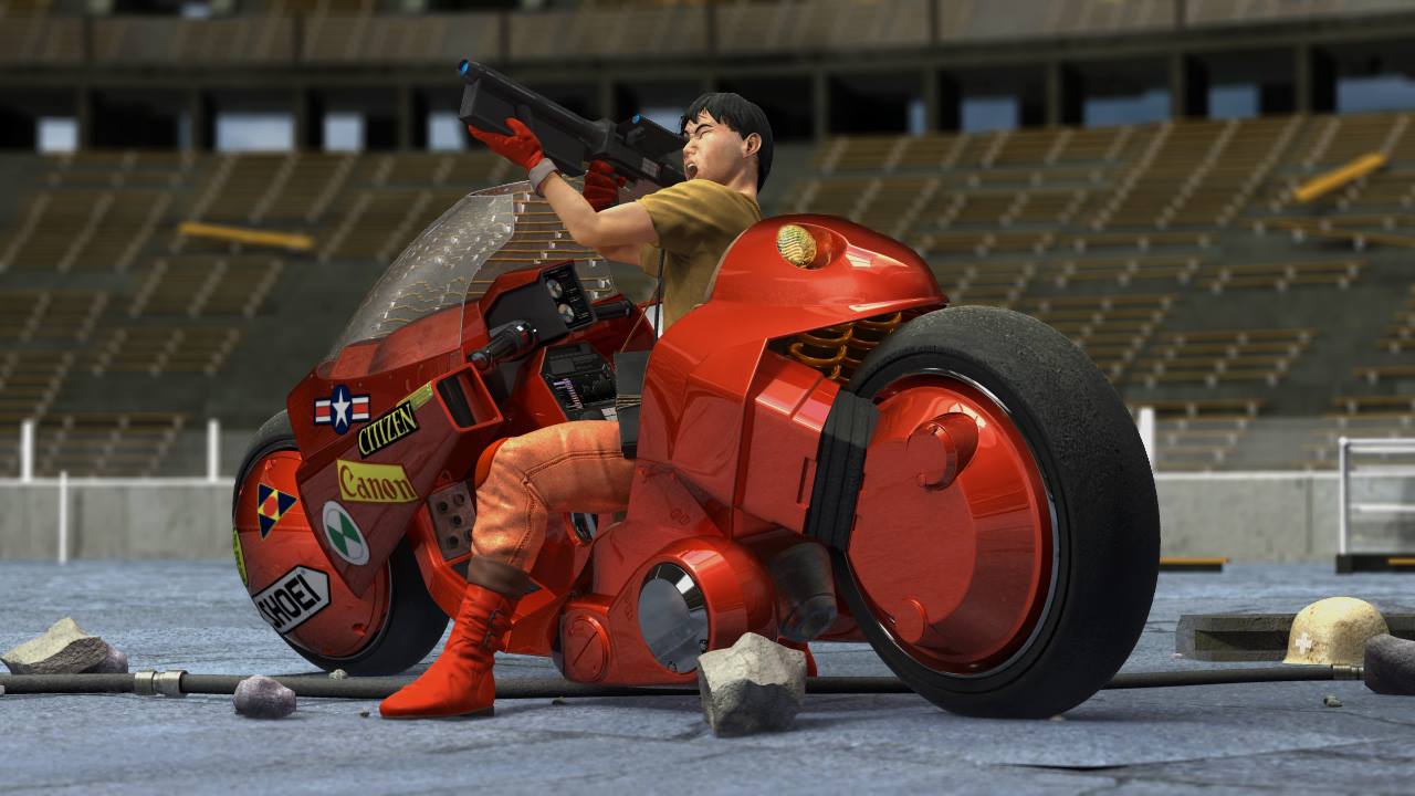
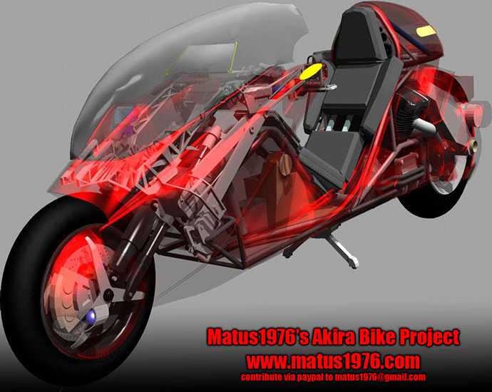
Lastly, here is one of my renders.
1 - 38
<
>

Help bring the fully functional high performance production Akira inspired motorcycle into existence...


Contribute through Amazon affilicate purchases
Donate directly
go to crowdfund for more options
send donations to


